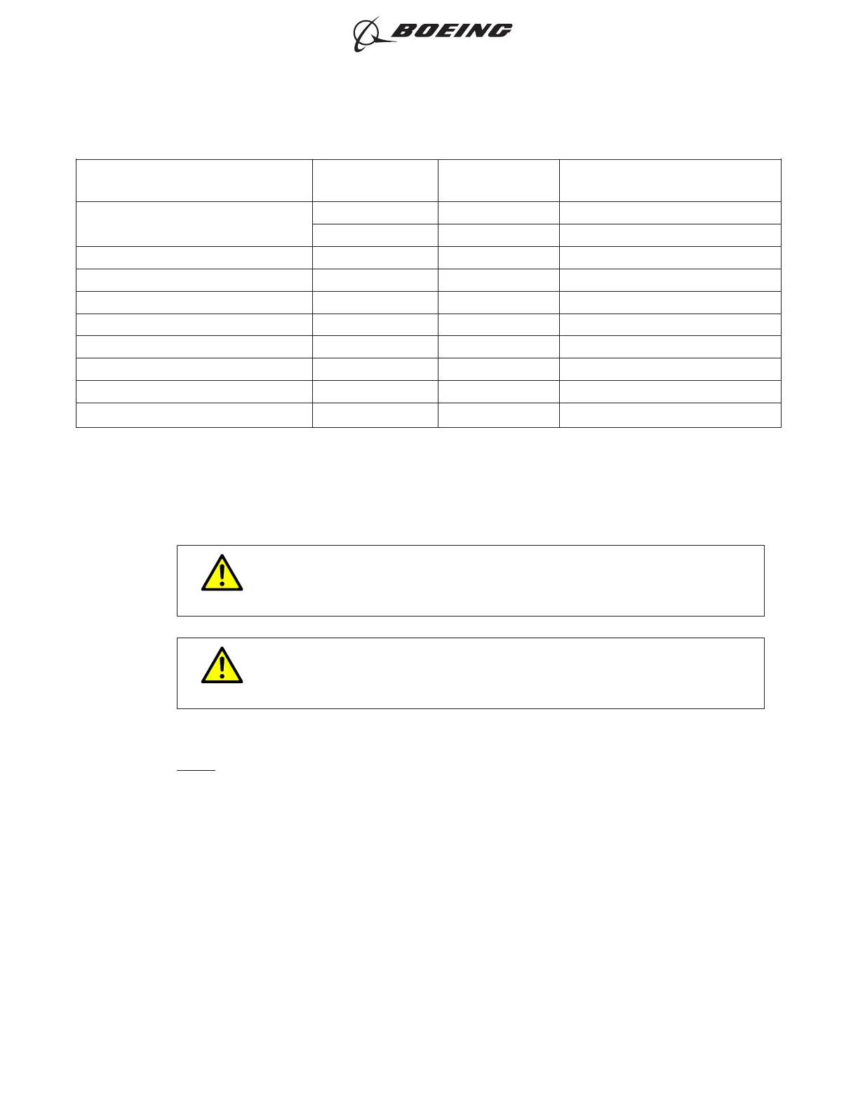
Table 12 O.D. OF THE WIRE INSULATION (Continued)
Boeing Part Number
Wire Size AL
(AWG)
Wire Size Cu
(AWG)
O.D. of the Wire Insulation Range
(inch)
BACS52N-48
4AL - .276-.305
- 8CU .210-.255
BACS52N-4A78 2AL 4CU .381-.417
BACS52N-5 1/0AL 2CU .425-.470
BACS52N-5A78 1/0AL 2CU .465-.513
BACS52N-6 2/0AL 1/0CU .500-.550
BACS52N-6A78 2/0AL 1/0CU .520-.574
BACS52N-7 3/0AL 2/0CU .520-.645
BACS52N-7A78 3/0AL 2/0CU .571-.633
BACS52N-8A78 4/0AL 3/0CU .615-.683
(1) Measure the O.D. of the wire insulation on each wire that must have a splice.
(2) Make a selection of one of these splices, refer to Table 12 for the O.D. of the wire insulation range
each splice takes:
• A standard butt splice; refer to Paragraph 2.A.
• A transitional butt splice; refer to Paragraph 2.B..
CAUTION
THE O.D. OF THE WIRE INSULATION IS VERY IMPORTANT. MAKE SURE
THAT FOR THE SPECIFIED SPLICE IN TABLE 12, THE O.D. OF THE WIRE
INSULATION IS NOT MORE THAN MAXIMUM O.D. SPECIFIED.
CAUTION
IF THE O.D. OF THE WIRE IS LESS THAN THE MINIMUM O.D. SPECIFIED.
THE O.D. OF THE INSULATION MUST BE INCREASED TO MAKE A SEAL
IN THE SPLICE. REFER TO STEP 4.E.(6).
(3) Make a selection of cold shrink sleeve from Table 8.
NOTE: A satisfactory alternative is a minimum of two layers of self-bonding silicone tape that are
applied after the splice is assembled. Refer to Paragraph 4.K..
(4) If a cold shrink sleeve is used, put the cold shrink sleeves on one end of the wire.
(5) Remove the necessary length of the insulation from the end of each wire.
Make sure that the end of each wire has not been crimped before.
Refer to:
• Table 13
• Subject 20-00-15.
(6) If the O.D. of the wire insulation is less than the minimum O.D. specified in Table 12, increase the
O.D. of the wire.
For the procedure to increase the O.D. of the wire insulation with:
ASSEMBLY AND REPAIR OF THE AMP AND BACS52N COPALUM SPLICES
707, 727-787
STANDARD WIRING PRACTICES MANUAL
20-30-13
Page 14
Oct 15/2017D6-54446
ECCN 9E991 BOEING PROPRIETARY - See title page for details