WARNING
PERSONAL INJURY CAN OCCUR IF:
• THE DIES ARE NOT CORRECTLY INSTALLED IN THE CRIMP HEAD
• THE POWER UNIT PIN IS NOT AGAINST THE YOKE.
(6) Put a small quantity of release agent on the crimp area of the dies.
(7) Put the end of one of the wires in the crimp barrel of the splice. Refer to Figure 7.
Make sure that:
• If the end of the splice has a blue ring, the wire in that end of the splice is a copper wire
• All of the conductor strands are in the crimp barrel
• The end of the wire insulation is against the funnel.
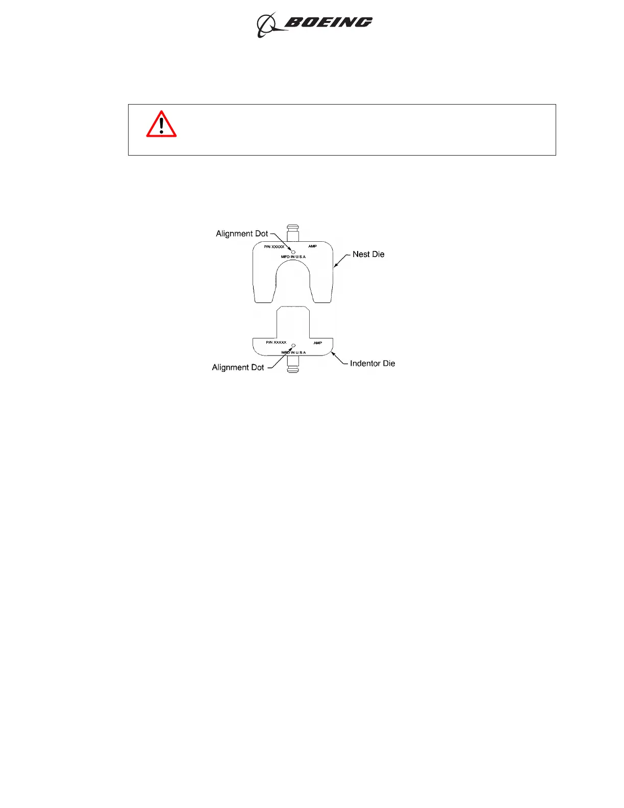
POSITION OF THE NEST DIE AND INDENTOR DIE
Figure 6
ASSEMBLY AND REPAIR OF THE AMP AND BACS52N COPALUM SPLICES
707, 727-787
STANDARD WIRING PRACTICES MANUAL
20-30-13
Page 21
Jun 15/2021D6-54446
ECCN 9E991 BOEING PROPRIETARY - See title page for details