(9) For a cable where the shield is folded back, install the other solder sleeve at the end of the shield
material. Refer to Subject 20-10-15 for the procedure to install a solder sleeve
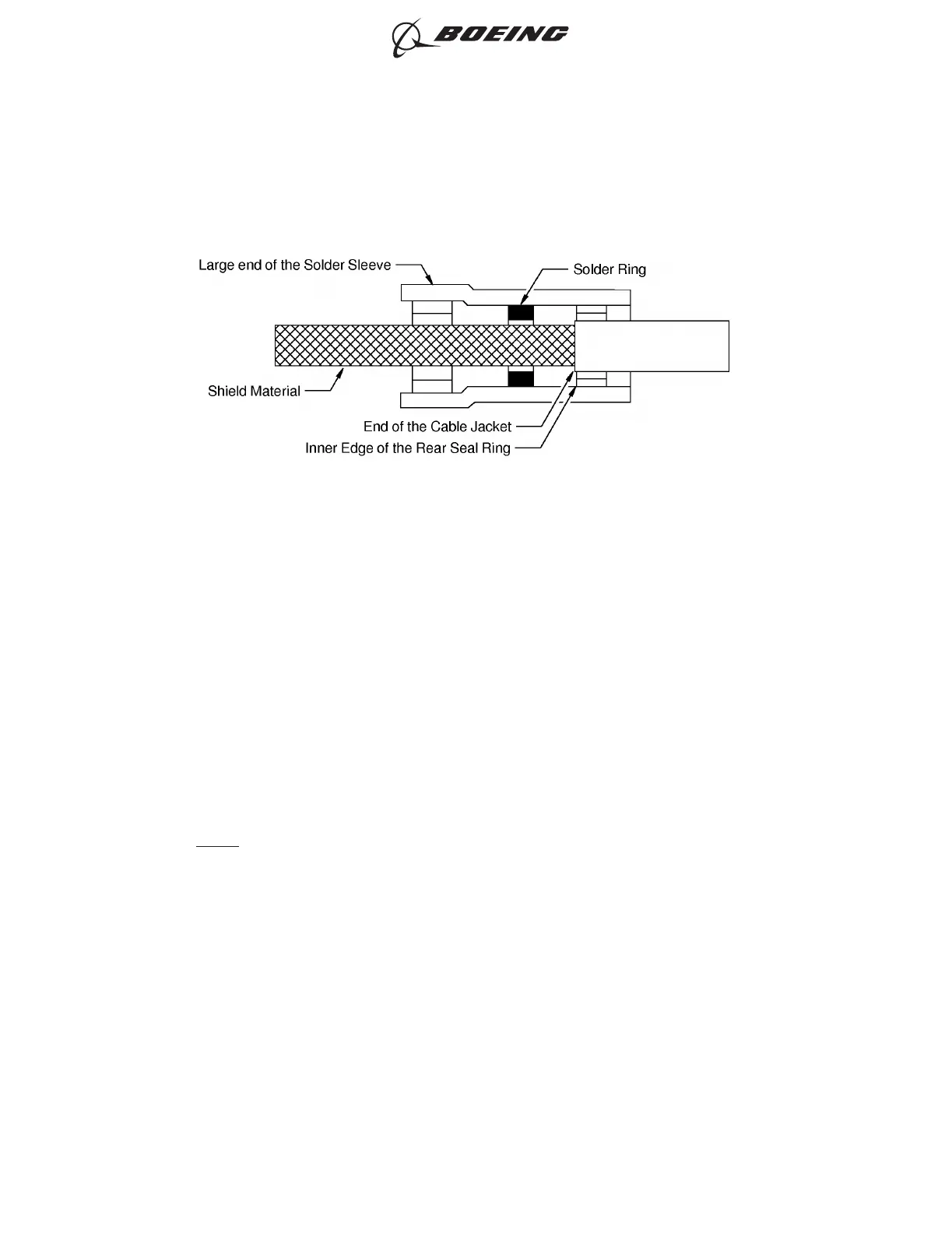
Make sure that:
• The rear edge of the solder ring is approximately 0.1 inch from the end of the shield material
• The rear seal ring does not make an overlap with the shield
• The heat is applied at the end of the solder sleeve that is on the shield material first
• The heat applied at the other end of the solder sleeve to melt it around the cable jacket
• The heat applied at the center of the solder sleeve and the cable is turned in the reflector
until the solder melts.
NOTE: A change of the color of the sleeve is permitted if the solder joint can be seen.
(10) If it is applicable, push each seal insert forward until the forward end is against the solder sleeve
on each end of the splice assembly.
(11) If one build-up sleeve is on the wiring:
(a) Push the sleeve forward until the forward end is against the solder sleeve.
(b) Shrink the sleeve into its position. Refer to Subject 20-10-14.
Make sure that:
• The sleeve has a tight fit on the wiring
• The forward end of the sleeve is not farther than 0.1 inch rearward from the end of the
solder sleeve.
(12) If two build-up sleeves are on the wiring:
POSITION OF THE SOLDER SLEEVE ON THE SHIELD MATERIAL
Figure 6
ASSEMBLY OF BACS52P SERIES AND D-150-0300 SERIES SHIELDED SPLICE ASSEMBLIES
707, 727-787
STANDARD WIRING PRACTICES MANUAL
20-30-20
Page 74
Jun 15/2021D6-54446
ECCN 9E991 BOEING PROPRIETARY - See title page for details