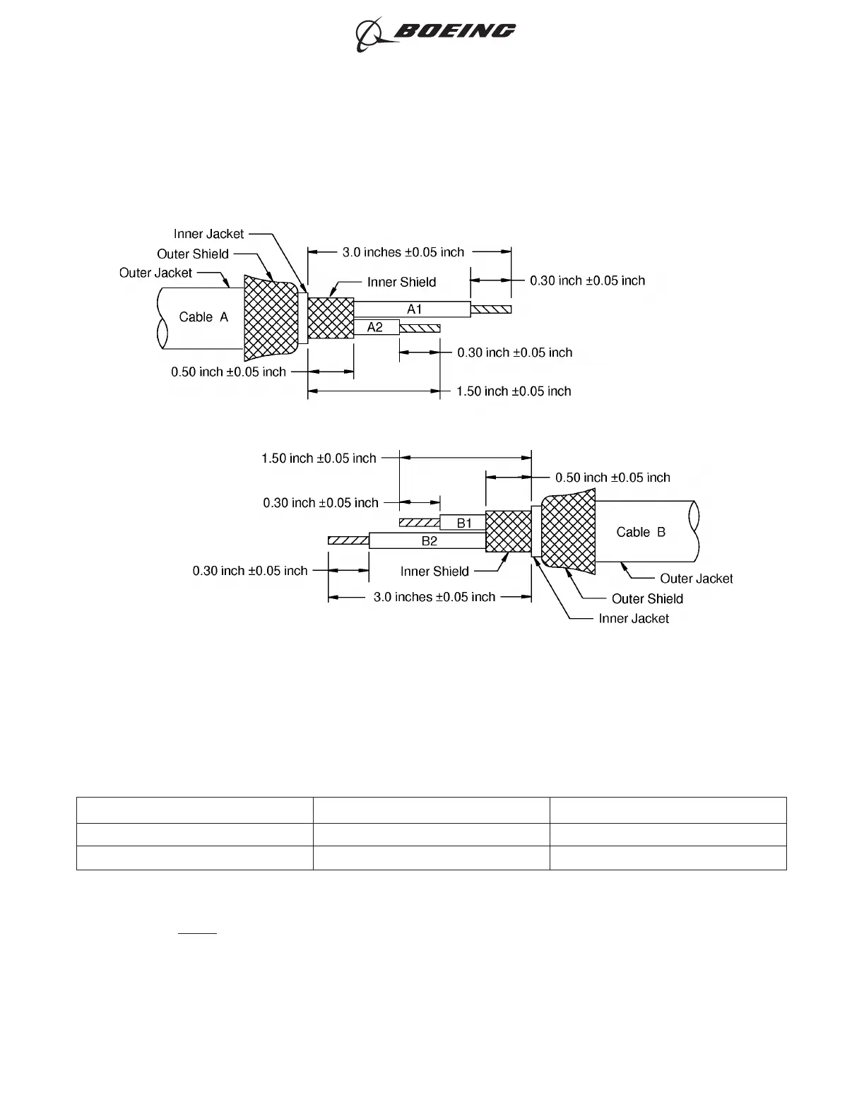
Table 30
CONNECTIONS
Wire Connection Wire Connected to
A1 Splice B1
A2 Splice B2
(4) Remove approximately 0.05 inch from each end of the shield material with a pair of scissors or an
equivalent tool.
NOTE: The shield material has fused ends that hold the ends of the strands of the shield
together.
(5) If the splice kit has seal inserts and different size solder sleeves:
ONE CLASS 2 CABLE WITH ISOLATED SHIELDS TO ONE CLASS 2 CABLE WITH ISOLATED SHIELDS
Figure 30
ASSEMBLY OF BACS52P SERIES AND D-150-0300 SERIES SHIELDED SPLICE ASSEMBLIES
707, 727-787
STANDARD WIRING PRACTICES MANUAL
20-30-20
Page 128
Oct 15/2021D6-54446
ECCN 9E991 BOEING PROPRIETARY - See title page for details