(8) If it is applicable, push each seal insert forward until the forward end is against the solder sleeve
on each end of the splice assembly.
(9) If a build-up sleeve is on the wiring:
(a) Push the sleeve forward until the forward end is against the solder sleeve.
(b) Shrink the sleeve into its position. Refer to Subject 20-10-14.
Make sure that:
• The sleeve has a tight fit on the wiring
• The forward end of the sleeve is not farther than 0.1 inch rearward from the end of the
solder sleeve.
(10) Align the center of the outer sleeve with the center of the shield material.
Make sure that each end of the sleeve makes a minimum of a 0.3 inch overlap with the jacket of
the cable.
(11) Shrink the sleeve into its position. Refer to Subject 20-10-14.
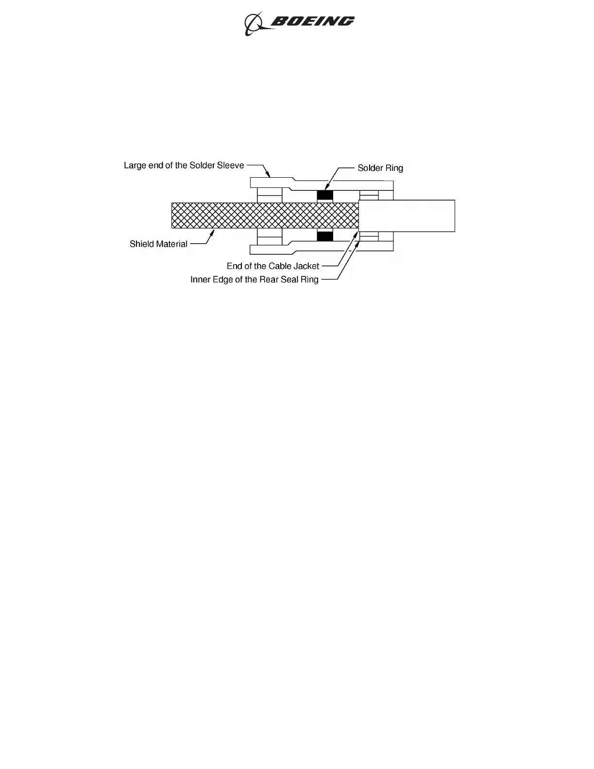
POSITION OF THE SOLDER SLEEVE ON THE SHIELD MATERIAL
Figure 6
ASSEMBLY OF BACS52T SERIES SHIELDED SPLICE ASSEMBLIES
707, 727-787
STANDARD WIRING PRACTICES MANUAL
20-30-21
Page 25
Jun 15/2021D6-54446
ECCN 9E991 BOEING PROPRIETARY - See title page for details