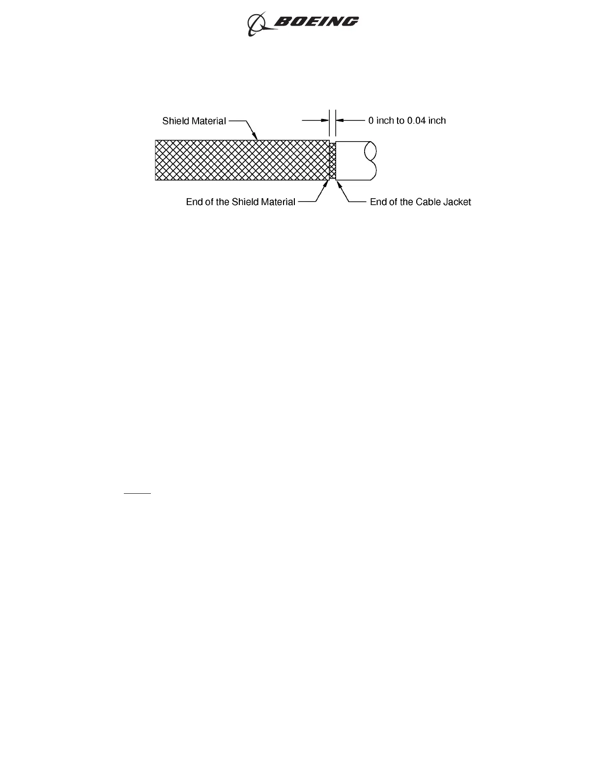
(5) If the shield material makes an overlap with the cable jacket, remove the unwanted length with
scissors or an equivalent tool.
(6) Twist the end of the shield material until it is tight against the shield of the cable.
(7) Install the other solder sleeve at the end of the shield material.
Refer to:
• Figure 6
• Subject 20-10-15 for the procedure to install the solder sleeve
Make sure that:
• The rear edge of the solder ring is approximately 0.1 inch from the end of the cable jacket
• The rear seal ring does not make an overlap with the shield
• The heat is applied at the end of the solder sleeve that is on the shield material first
• The heat applied at the other end of the solder sleeve to melt it around the cable jacket
• The heat applied at the center of the solder sleeve and the cable is turned in the reflector
until the solder melts.
NOTE: A change of the color of the sleeve is permitted if the solder joint can be seen.
POSITION OF THE SHIELD MATERIAL AT THE END OF THE CABLE JACKET
Figure 5
ASSEMBLY OF BACS52T SERIES SHIELDED SPLICE ASSEMBLIES
707, 727-787
STANDARD WIRING PRACTICES MANUAL
20-30-21
Page 24
Oct 15/2020D6-54446
ECCN 9E991 BOEING PROPRIETARY - See title page for details