(2) If the conductor splice has a seam, put the seam on the same side as the indenter.
(3) Slowly close the jaws of the tool until the splice is held in position.
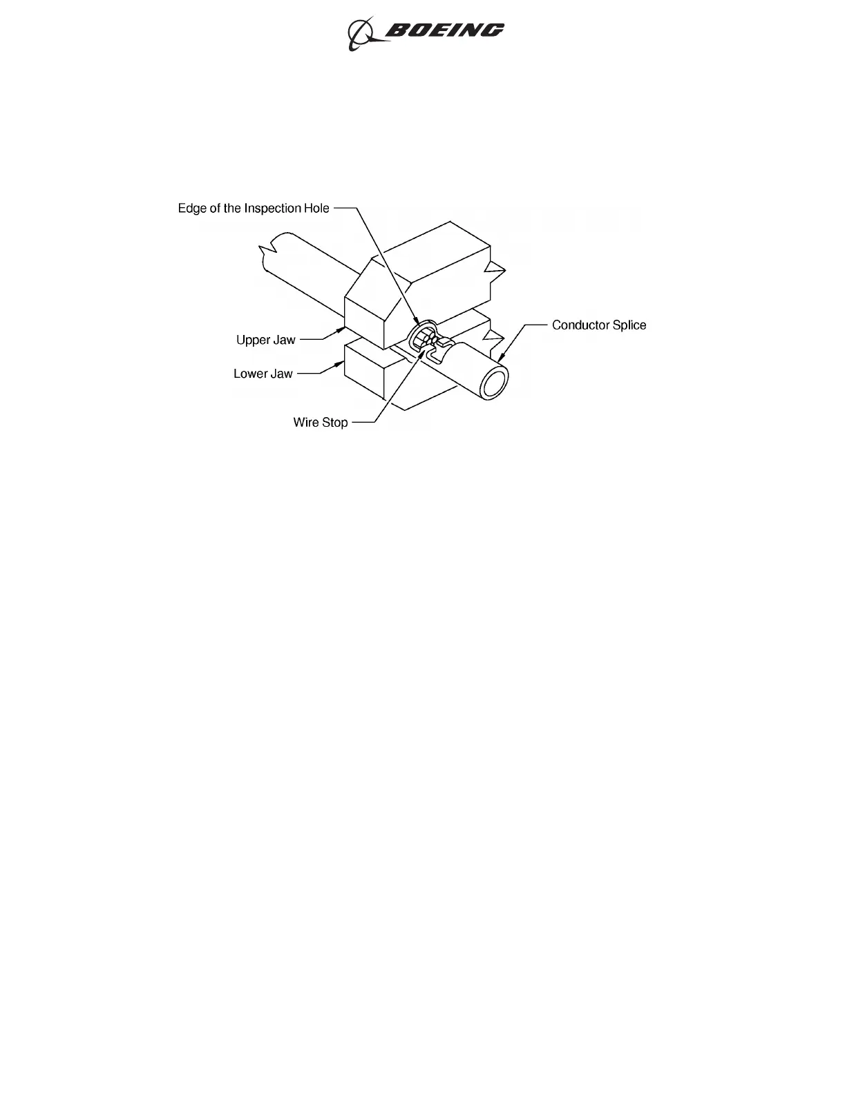
(4) If it is necessary, adjust the position of the conductor splice in the crimp tool to make sure that the
crimp occurs on correct location on the crimp barrel.
(5) Put the necessary conductors in one end of the conductor splice. Refer to Figure 42.
Make sure that the end of each conductor is against the wire stop in the center of the conductor
splice.
(6) If a filler wire is specified, remove the unwanted length of the filler wire to make the distance from
the end of the crimp barrel to the end of the filler wire equal to 0.06 inch or shorter. Refer to
Figure 43.
POSITION OF THE CONDUCTOR SPLICE IN THE CRIMP TOOL
Figure 42
ASSEMBLY OF BACS52T SERIES SHIELDED SPLICE ASSEMBLIES
707, 727-787
STANDARD WIRING PRACTICES MANUAL
20-30-21
Page 109
Jun 15/2021D6-54446
ECCN 9E991 BOEING PROPRIETARY - See title page for details