Inspection Mode
3-6 Manual # 42-02-7223
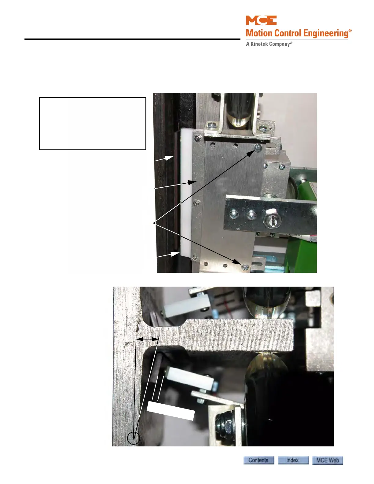
5. Place a magnet on the rail as shown in Figures 4 and 5. below. iLand Compact must be
adjusted so that the Leveling Sensors are centered on the magnet with the face of the
sensor board 1/4 inch (K 1/16 inch) from the surface of the magnet. Magnets may be
stacked to increase height if needed.
Figure 4. Magnet position on the rail (side view)
Figure 5. Magnet position on the rail (top view)
Front Door Floor Leveling Magnet
Front Door Leveling Sensors
Note: The front door floor leveling
magnet and leveling sensors are
shown in this picture (left side).
The rear door floor leveling magnet
and sensors, if applicable, are
mounted on the right side of the
rail (See Figure 5).
Leveling Sensor Bracket
Leveling Sensor Bracket
adjustment screws
12 degrees
The magnet should be
on an angle of approx-
imately 12 degrees
with respect to the
back surface of the
rail.
1
/
4
”
K
1
/
1
6
”
The Leveling Sensors
should line up with the
center of the magnet
with the face of the
sensor board 1/4”
(
K 1/16”) from the
surface of the magnet.
Magnets may be
stacked to increase
height if needed.
R
e
ar
S
e
n
so
r
s
F
r
o
n
t
S
e
n
so
r
s