iView - Controller View
9-110 Manual # 42-02-7223
Notch Filter Enables the current notch filter for the System 12 SCR drive. When enabled,
Process Notch Frequency, Quality, and Depth parameters are active, allowing a specific, calcu-
lated frequency (range) to be blocked. It is important to be certain that the oscillation is in fact
mechanically induced into the speed feedback signal and not a result of improperly adjusted
system gains or dampening. Typically an induced oscillation is low frequency (2 to perhaps
15Hz) and may occur only while running at steady speed through a particular section of the
hoistway. If the oscillation meets this criteria, it may be a candidate for notch filtering.
• Notch filter: Enables/disables the Notch filter.
• Process notch frequency (0 - 200): Notch filter frequency. Determines what frequency is
to be blocked.
• Process notch bandwidth “Q” (1 - 100): Notch filter bandwidth. Adjusts the frequencies at
which filtering begins and ends. Lower values cause more gradual shoulders in the notch
(see illustration), beginning filtering sooner and ending it later. (A wider frequency range
is suppressed.)
• Process notch depth (1 - 100,000): Notch filter center depth. Higher values cause greater
attenuation of the selected frequency.
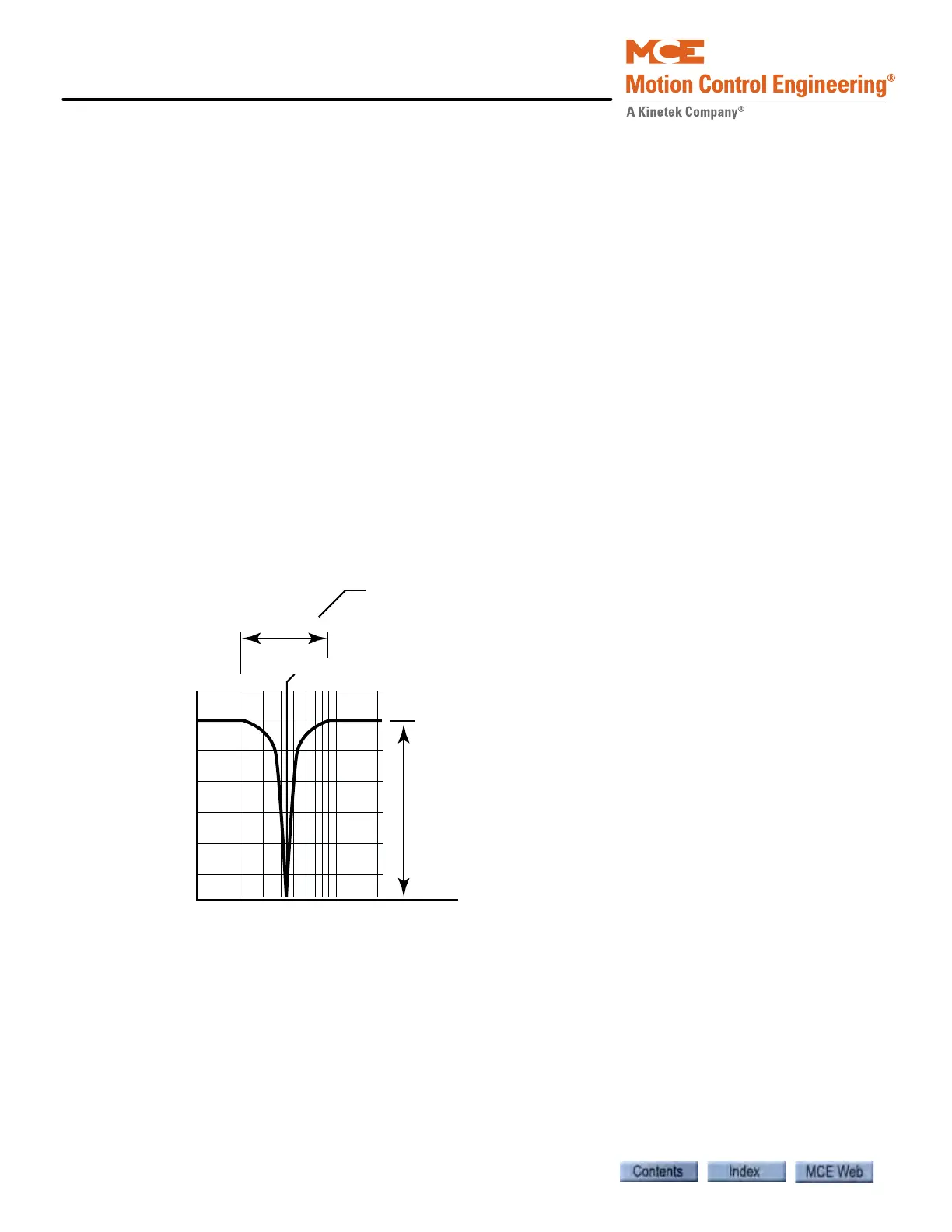
The following illustration shows the function of a typical notch filter labeled to clarify the con-
cept and the results of adjustment.
Figure 9.2 Notch Filter Characteristics
Gain (dB)
Frequency (Hz)
10
0
-10
-20
-30
-40
-50
-60
0 100
Process Notch Frequency
Bandwidth
Process Notch Depth
Quality Factor (Q= Frequency/Bandwidth)