Configuration - Drive
9-111
9
iControl DC
Notch Settings When setting the notch filter, you can determine the “center” frequency
of the oscillation using an oscilloscope. This frequency is what you enter as the Process Notch
Frequency. The other two settings (Bandwidth and Depth) are more subjective and you will
need to experiment to find the best setting.
Notch Filtering removes a “center” frequency and some surrounding frequencies (depending on the
bandwidth or Q setting) from the speed command to the drive. If improperly used, notch filtering
may remove a legitimate control frequency, resulting in poor system control.
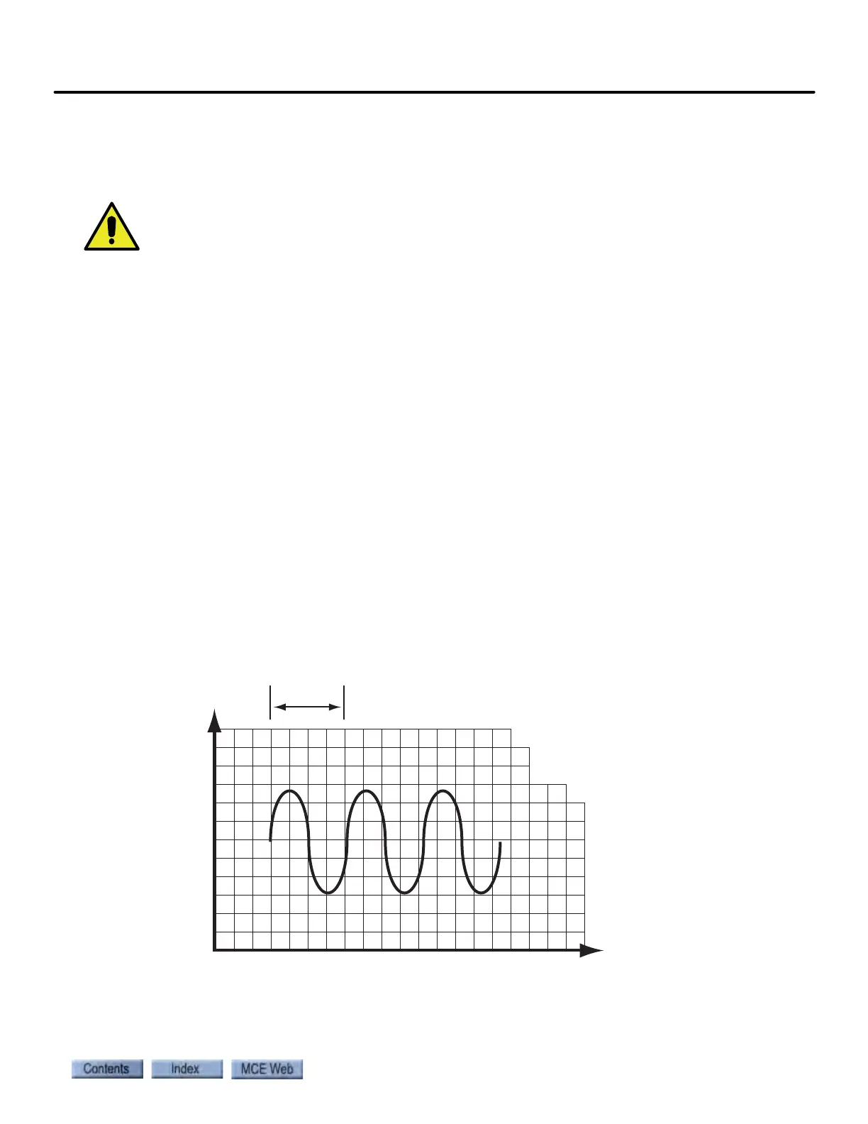
• Use an oscilloscope to monitor the Speed Feedback signal. (See the following illustration.)
• Adjust the oscilloscope to determine the Time it takes the oscillation frequency to com-
plete one full cycle. (It may be easier to determine the time for “n” cycles. If so, use the for-
mula T
1
= T
n
/ n.)
•Use the formula 1/T
1
(single cycle time) = Frequency.
• Set Process Notch Frequency to the calculated frequency
• Determine and set Q value. The frequency of the oscillation might vary a little. If you can
determine bandwidth (range) of the frequencies to be blocked, you may use the formula
Q=Frequency/Bandwidth to calculate a beginning point for the bandwidth (Q) value. The
object is to use the highest Q value possible (the narrowest possible notch). It is important
to keep the notch as narrow as possible to avoid blocking legitimate control frequencies
and making car operation unstable.
• Set Process Notch Depth. The range is from 1 to 100,000. Start out using the maximum
setting for the most complete suppression of the selected frequency. You may have to
experiment with reducing the setting in fixed increments to achieve the best results.
• Monitor the signal and modify Q and Notch in defined increments until you reach the best
possible balance between system control and reduced oscillation.
Figure 9.3 Determine Frequency of Oscillation
Time (T)
Time
Amplitude
Frequency = 1/T
Q = Frequency/Bandwidth