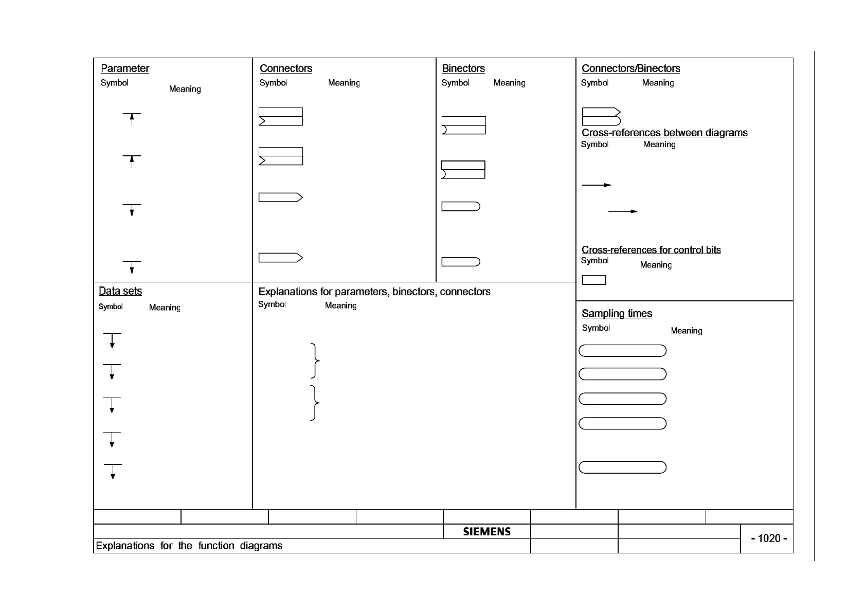
Fig. 3-1 1020 – Explanation of the symbols (part 1)
fp_1020_89.vsd
12345678
SINAMICS DCP
03.06.2014 v 1.2
DO: All Objects
- Explanation of the symbols (part 1)
Function diagram
(xxxx [y])
pxxxx[y...z]
(xxxx [x])
pxxxx[y]
rxxxx[y...z]
rxxxx[y]
(Def.x)
pxxxx[y...z]
(Def.x)
pxxxx[y]
rxxxx
rxxxx.yy
rxxxx
rxxxx
[aaaa.b]
pxxxx
pxxxx[P]
pxxxx[M]
pxxxx[E]
pxxxx[D]
pxxxx[C]
[1020.7]
[1020.7]
pxxxx[Y] (ZZZ.ZZ μs)
PROFIdrive sampli ng time
CAN bus sampling time
Background
Not relevant
Display parameter
(parameter may appear
multiple times)
Display parameter with
index (parameter may
appear multiple times)
Adjustable parameter
(if parameter appears
multiple times, diagram
references are specified).
Adjustable parameter with
index
(if parameter appears
multiple times, diagram
references are specified).
Connector input CI with index
range [y...z]
Connector input CI with index [y]
Connector output CO with [unit]
and index range [y...z]
(parameter may appear multiple
times)
Connector output CO [unit] and
with index [y]
(parameter may appear multiple
times)
Binector input BI with
index range [y...z] and
factory setting (Def.x) with
bit x.
Binector input BI
with index [y] and factory
setting (Def.x) with bit x.
Binector output BO
(parameter may appear
multiple times)
Binector output BO with
bit yy
(parameter may appear
multiple times)
Connector/binector output CO/BO
The function diagrams are divided into signal paths 1
to 8 to enable quicker navigation.
Text = Unique signal name
aaaa = Signal goes to destination diagram aaaa
b = Signal goes to signal path b
Text = Unique signal name
cccc = Signal comes from source diagram cccc
d = Signal comes from signal path d
To "Function diagram name" [aaaa.b] = For binectors
pxxxx = Original parameter of signal
aaaa = Signal comes from source diagram aaaa
b = Signal comes from signal path b
Adjustable parameter with factory setting
for selecting time slice.
Default in p2048.
Time slice 4,000.00 μs.
There is no fixed sampling time for this
function. Processing takes place in the
background.
The cycle time depends on the Control
Unit's computational load.
A static state is represented here. The
sampling time data is not relevant.
Parameter belongs to Command
Data Set (CDS).
Parameter belongs to Drive Data
Set
(DDS).
Parameter belongs to Encoder
Data Set
(EDS).
Parameter belongs to Motor Data
Set
(MDS).
Parameter belongs to Power Unit
Data Set (PDS)
Parameter name [unit]
rxxxx [x...y]
Parameter name [unit]
Index name
rxxxx[x]
[aaaa.b]
Parameter name
from ... to [unit]
pxxxx[y...z] (Def)
[aaaa.b]
Parameter name
Index name
from ... to [unit]
pxxxx[y] (Def)
Parameter name
Parameter name Index name
Parameter name
[unit]
Parameter name [unit]
Index name
Parameter name
Parameter name Bit
name
Parameter name
Parameter name
Bit name
Parameter name
Signal path
Text
Text
[cccc.d]
[aaaa.b]
Parameter name
[Unit]
rxxxx[y] or rxxxx[y...z]
or
rxxxx[y].ww or
rxxxx.ww
pxxxx[y] or pxxxx[y...z]
or
pxxxx[y].ww or
pxxxx.ww
from ... to
(xxxx[y].ww)
(Def)
(Def.w)
Name of parameter (max. 18 characters)
[Unit]
"r" = Display parameter. Parameters of this type are read-only.
"xxxx" stands for the parameter number.
"[y]" specifies the valid index, while "[y...z] specifies the applicable index range.
".ww" speci
[aaaa.b]