(5) Put the wire in the splice. Refer to Figure 16.
Make sure that when the wire is in the splice:
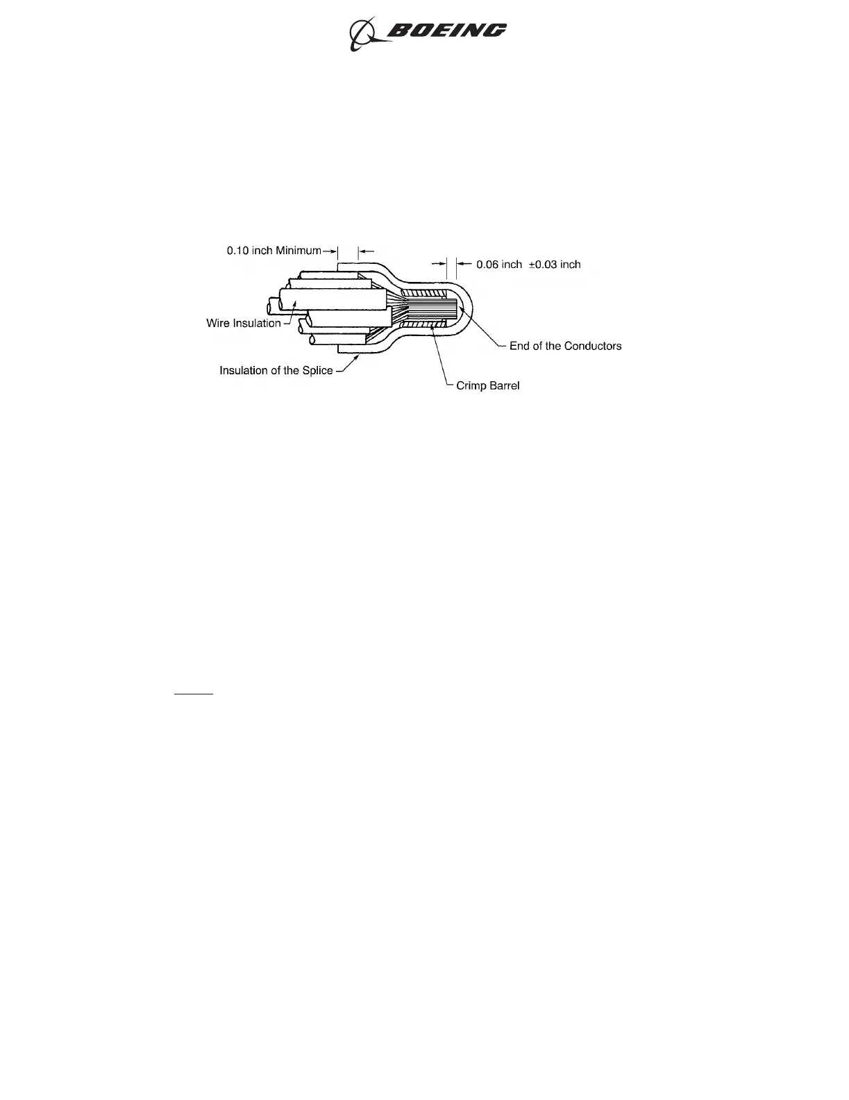
• The insulation of the splice makes a 0.1 inch minimum overlap with the wire insulation
• The wire insulation is not in the crimp barrel of the splice
• The distance from the end of the conductor to the end of the crimp barrel of the splice is
0.06 inch ±0.03 inch.
NOTE: The wire insulation, the crimp barrel, and the conductor can be seen through the
insulation of the closed end splice.
(6) If it is necessary, remove more insulation from the end of the wire to make a correct fit of the wire
in the splice.
(7) Put the splice in the crimp tool.
(8) Hold the splice in position with light pressure.
(9) Put each wire in the splice. Refer to Figure 16.
Make sure that each wire is in the correct position.
(10) Crimp the splice. Refer to Figure 17.
Make sure that the shoulder of the insulation on the splice is against the locator of the crimp tool.
POSITION OF EACH WIRE IN THE SPLICE
Figure 16
ASSEMBLY OF SPLICES
707, 727-787
STANDARD WIRING PRACTICES MANUAL
20-30-12
Page 61
Feb 15/2021D6-54446
ECCN 9E991 BOEING PROPRIETARY - See title page for details