Make sure that the sleeve has the smallest diameter that can be put on the wire and the splice.
NOTE: For alternative heat shrinkable sleeves, refer to Subject 20-00-11.
(5) Cut a 4.0 inch ±0.2 inch length of the sleeve.
(6) For an AWG 8 and larger wire, cut one more piece of the sleeve that is 2.4 inches ±0.2 inch in
length.
(7) Put the sleeves on the end of one of the wires.
(8) Remove the necessary length of insulation from the end of each wire.
Refer to:
• Figure 30
• Table 64 for the insulation removal length
• Subject 20-00-15 for the insulation removal procedures.
(9) Assemble one end of the butt splice:
(a) Put the splice in the crimp tool.
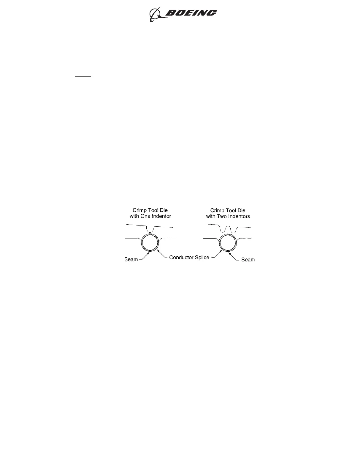
(b) If the splice has a seam, align the seam opposite the indenter. Refer to Figure 31.
(c) Hold the splice in position with light pressure.
(d) Put the wire in the end of the splice. Refer to Figure 32.
Make sure that:
• The end of the conductor can be seen in the inspection hole
• The end of the conductor does not make an overlap with the wire stop
• The wire insulation is not in the crimp barrel
• For AWG 10 and smaller wire, the end of the wire insulation is a maximum of 0.13 inch
from the end of the crimp barrel
• For AWG 8 and larger wire, the end of the wire insulation is a maximum of 0.25 inch
from the end of the crimp barrel.
POSITION OF THE BUTT SPLICE IN THE CRIMP TOOL
Figure 31
ASSEMBLY OF SPLICES
707, 727-787
STANDARD WIRING PRACTICES MANUAL
20-30-12
Page 74
Feb 15/2021D6-54446
ECCN 9E991 BOEING PROPRIETARY - See title page for details