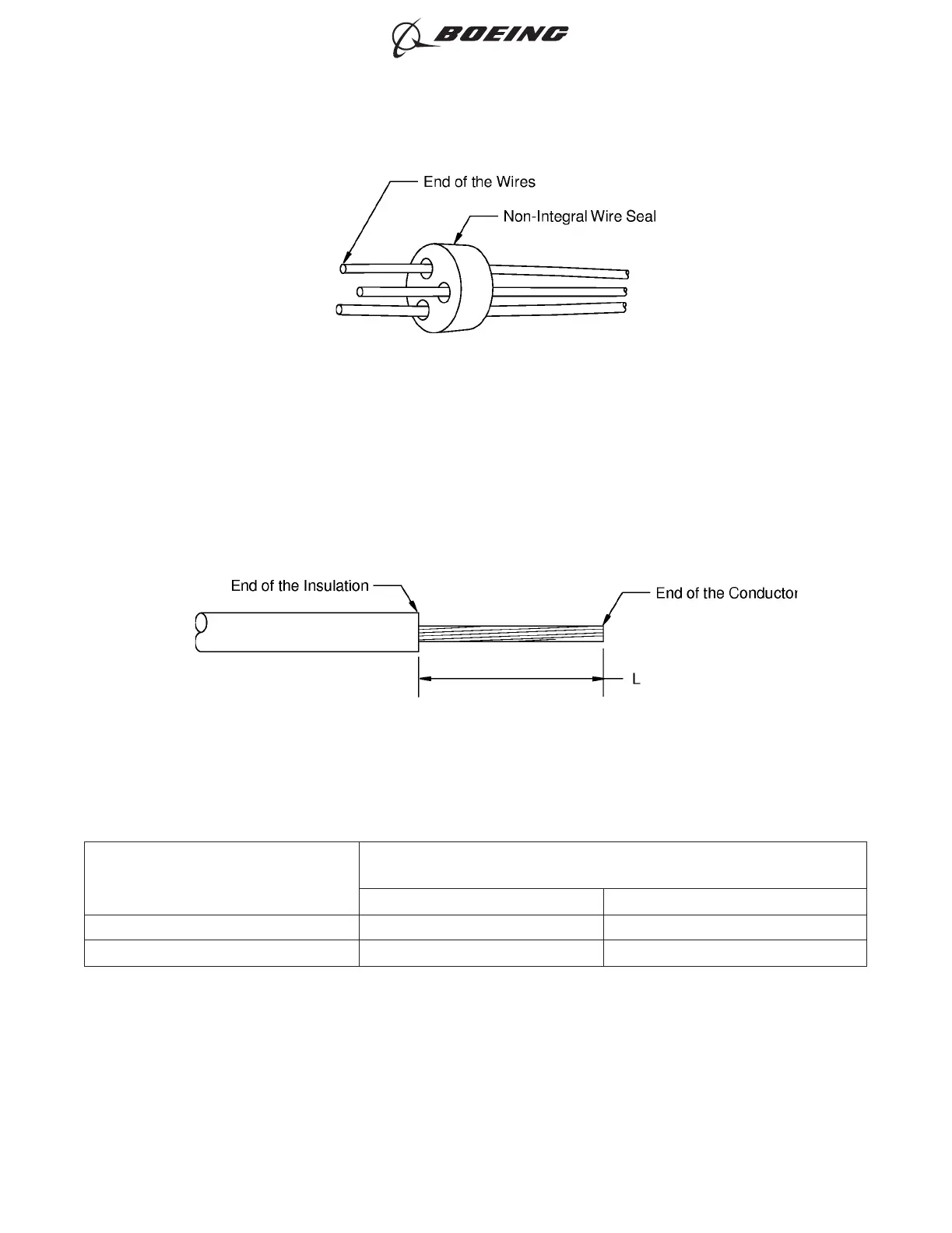
(7) Remove the necessary length of insulation from the end of each wire.
Refer to:
• Figure 75
• Table 75 for the insulation removal length
• Subject 20-00-15 for the insulation removal procedures.
Table 75
INSULATION REMOVAL LENGTH
Butt Splice Part Number
Insulation Removal Length L
(inch)
Target Tolerance
D-609-07 0.28 ±0.03
D-609-08 0.28 ±0.03
(8) Assemble one end of the butt splice.
(a) Put the splice in the crimp tool.
(b) Hold the splice in position with light pressure.
(c) Put all of the wires for one end of the splice in the crimp barrel. Refer to Figure 76 and
Figure 77.
NON-INTEGRAL WIRE SEAL ON THE WIRES
Figure 74
INSULATION REMOVAL LENGTH
Figure 75
ASSEMBLY OF SPLICES
707, 727-787
STANDARD WIRING PRACTICES MANUAL
20-30-12
Page 106
Feb 15/2021D6-54446
ECCN 9E991 BOEING PROPRIETARY - See title page for details