Make sure that the wires are in the correct position.
(d) Crimp the splice.
(10) Assemble the end of the butt splice with one wire.
(a) Put the splice in the crimp tool.
(b) Hold the splice in position with light pressure.
(c) Put the wire in the splice.
Refer to:
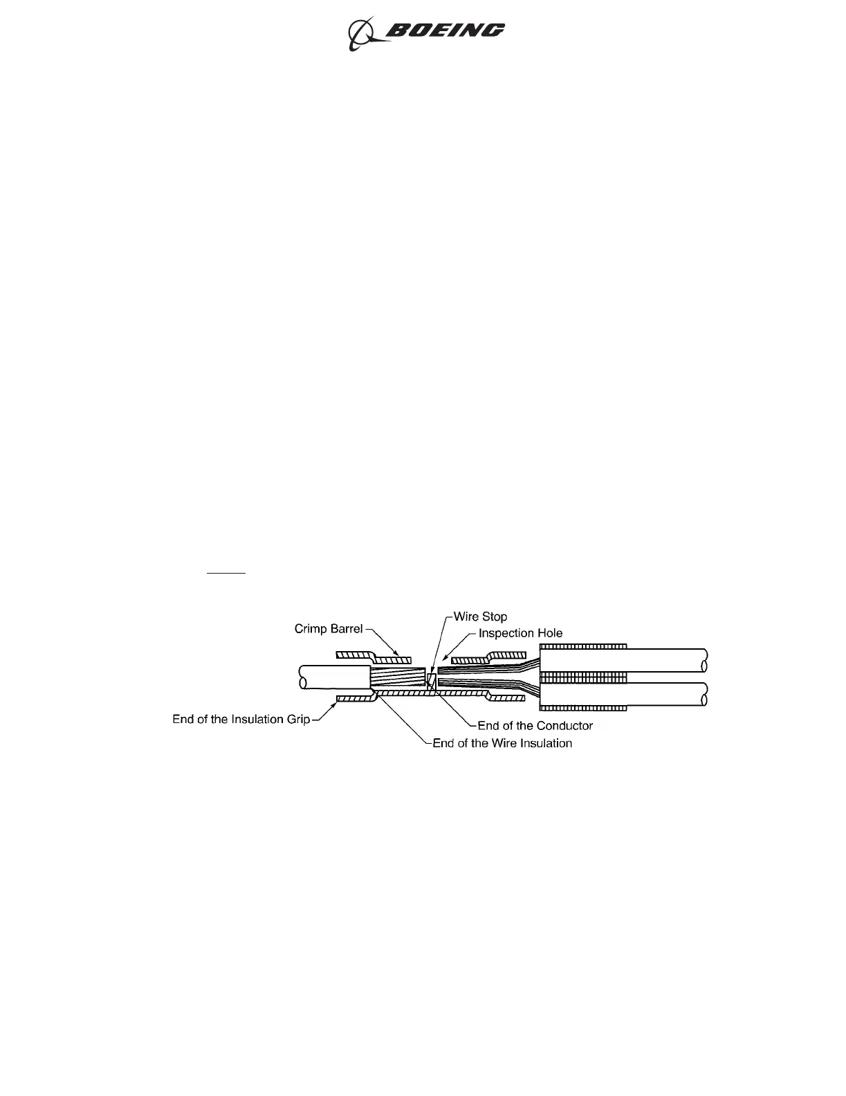
• Figure 104 for the position of the wire in the splice with the wire insulation in the
insulation grip
• Figure 105 for the position of the wire in the splice with the wire insulation out of the
insulation grip.
Make sure that:
• The end of the conductor can be seen in the inspection hole
• The end of the conductor does not make an overlap with the wire stop
• If the wire insulation can go into the insulation grip, the end of the wire insulation is in
the insulation grip
• If the wire insulation cannot go into the insulation grip, the end of the wire insulation is
a maximum of 0.13 inch from the end of the insulation grip
• The wire insulation is not in the crimp barrel.
NOTE: The insulation removal length can be changed to make these conditions
satisfactory.
POSITION OF THE WIRE IN THE BUTT SPLICE WITH THE WIRE INSULATION IN THE INSULATION GRIP
Figure 104
ASSEMBLY OF SPLICES
707, 727-787
STANDARD WIRING PRACTICES MANUAL
20-30-12
Page 131
Jun 15/2021D6-54446
ECCN 9E991 BOEING PROPRIETARY - See title page for details