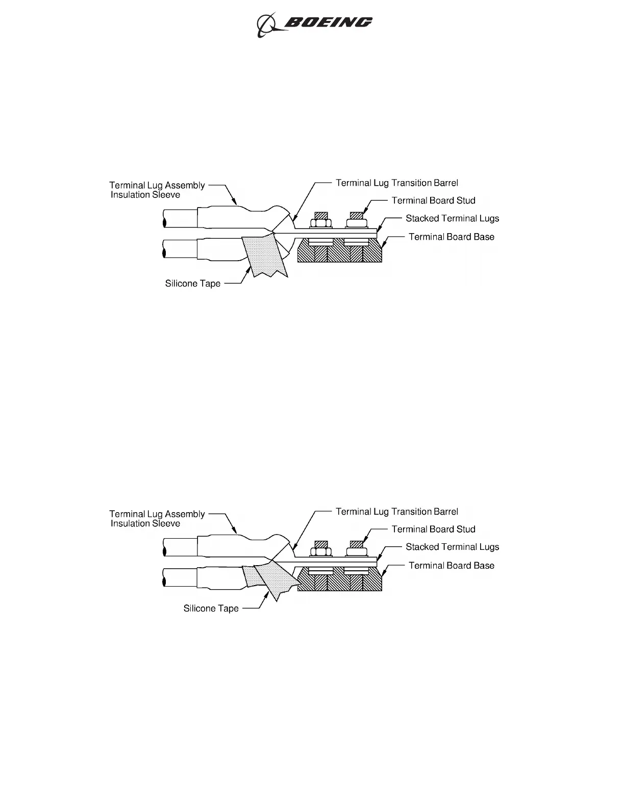
(3) Continue to wind the length of the tape tightly around the forward end of the insulation sleeve of
the first terminal lug. Refer to Figure 26.
INITIAL POSITION OF THE TAPE ON THE FIRST TERMINAL LUG
Figure 25
POSITION OF THE SECOND LAYER OF TAPE ON THE FIRST TERMINAL LUG
Figure 26
ELECTRICAL CONNECTION OF EQUIPMENT AND INSTALLATION OF TERMINAL LUGS
707, 727-787
STANDARD WIRING PRACTICES MANUAL
20-30-00
Page 33
Jun 15/2018D6-54446
ECCN 9E991 BOEING PROPRIETARY - See title page for details