Make sure that the splice has the smallest CAU range that can accept the total CAU of the
conductor.
(4) Find the crimp barrel size of the splice from Table 15.
(5) Make a selection of a crimp tool from Table 46.
(6) Make a selection of a Temperature Grade D insulation tape from Table 52.
Make sure that the tape has a width of 0.5 inch minimum to 1.0 inch maximum.
(7) Prepare each wire for the side of the splice assembly with two wires.
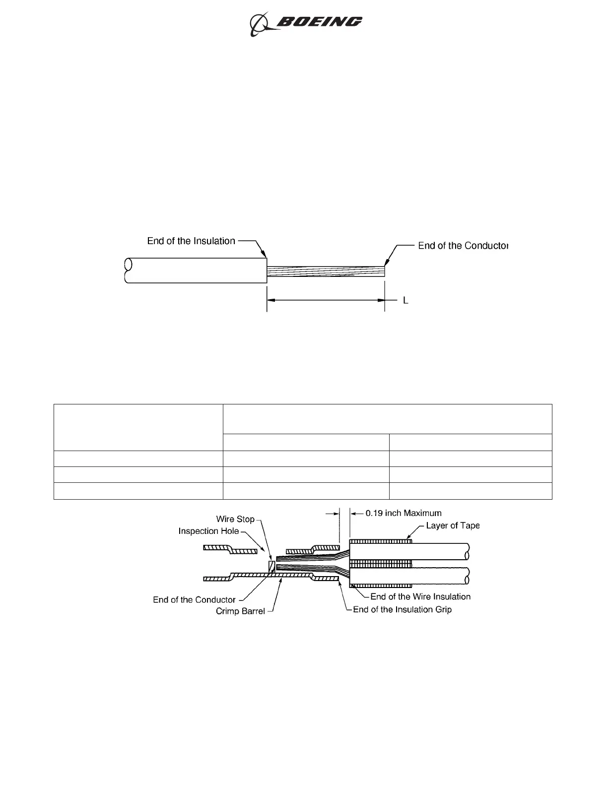
Table 97
INSULATION REMOVAL LENGTH
Splice Part Number
Insulation Removal Length L
(inch)
Target Tolerance
BACT12C11 0.46 ±0.02
BACT12C15 0.30 ±0.02
BACT12C20 0.30 ±0.02
(a) Remove the necessary length of insulation from the end of each wire.
Refer to:
INSULATION REMOVAL LENGTH
Figure 138
POSITION OF THE WIRES IN THE BUTT SPLICE
Figure 139
ASSEMBLY OF SPLICES
707, 727-787
STANDARD WIRING PRACTICES MANUAL
20-30-12
Page 163
Jun 15/2021D6-54446
ECCN 9E991 BOEING PROPRIETARY - See title page for details