(4) Make a selection of a Temperature Grade B or higher insulation tape from Table 52.
Make sure that the tape has a width of 0.5 inch minimum to 1.0 inch maximum.
(5) Prepare each shielded wire for the side of the splice assembly with two shielded wires.
Refer to:
• Figure 150
• Subject 20-00-15 for the outer jacket removal procedures.
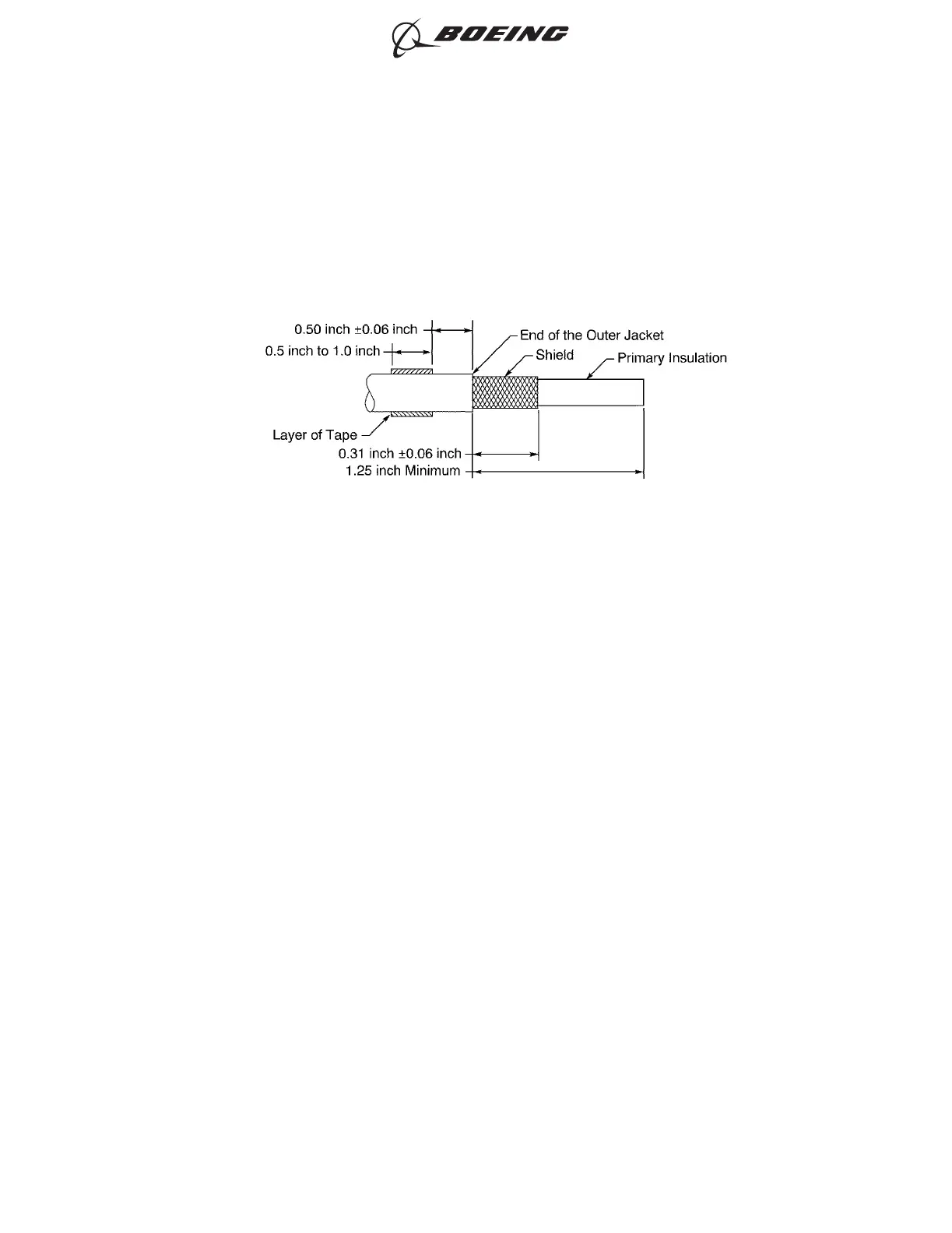
(a) Remove a 1.25 inch minimum length of the outer jacket from the end of the wire.
(b) Remove the necessary length of the shield from the end of the wire.
Make sure that the remaining shield is 0.31 inch ±0.06 inch.
(c) Wind a layer of the insulation tape on the outer jacket of each wire 0.50 inch ±0.06 inch
farther than the end of the outer jackets.
Make sure that:
• The tape goes around the circumference of the wire a minimum of two times
• The tape makes a 100 percent overlap.
(6) Prepare the end of the shielded wire for the side of the splice assembly with one shielded wire.
Refer to:
• Figure 151
• Subject 20-00-15 for the outer jacket and insulation removal procedures.
SHIELDED WIRE PREPARATION
Figure 150
ASSEMBLY OF SPLICES
707, 727-787
STANDARD WIRING PRACTICES MANUAL
20-30-12
Page 178
Jun 15/2021D6-54446
ECCN 9E991 BOEING PROPRIETARY - See title page for details