(4) Make a selection of a Temperature Grade D insulation tape from Table 52.
(5) Prepare the shielded cable.
Refer to:
• Figure 186
• Subject 20-00-15 for the outer jacket removal procedures.
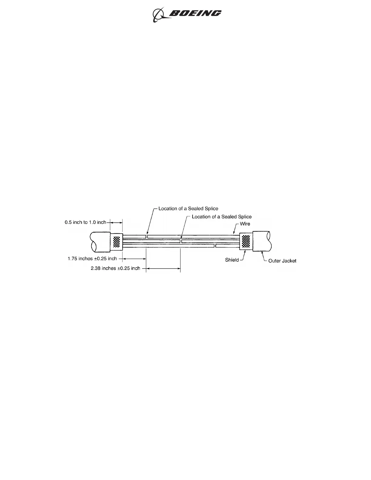
Make sure that:
• The distance from the end of the outer jacket to the end of the shield is 0.5 inch to 1.0 inch
• The distance from the end of the shield to the center of the nearest sealed splice is 1.75
inches ±0.25 inch
• The distance from the center of a sealed splice on one wire to the center of the nearest
sealed splice on another wire is 2.38 inches ±0.25 inch.
(6) Cut the necessary length of the shield sleeve material.
Make sure that the end of the shield sleeve material extends farther than the rear end of the inner
ferrule on each end of the shield splice.
(7) Put these components on the end of one cable:
• The outer ferrule
• The inner ferrule.
(8) Put these components on the end of the other cable:
• The outer ferrule
• The inner ferrule
PREPARATION OF THE SHIELDED CABLE
Figure 186
ASSEMBLY OF SPLICES
707, 727-787
STANDARD WIRING PRACTICES MANUAL
20-30-12
Page 227
Jun 15/2021D6-54446
ECCN 9E991 BOEING PROPRIETARY - See title page for details