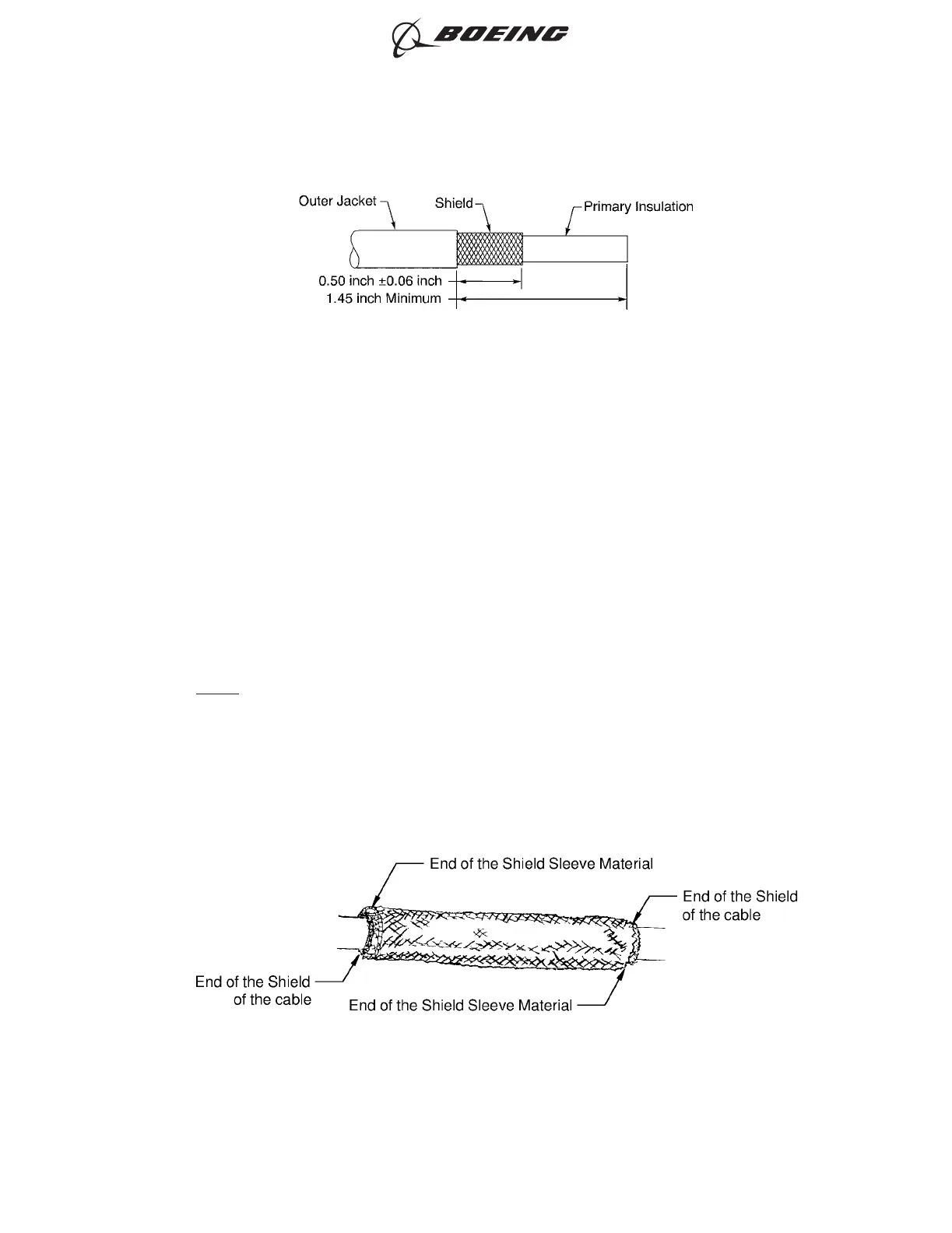
(a) Remove 1.45 inch minimum length of outer jacket from the end of the wire.
(b) Remove the necessary length of the shield from the end of the wire.
Make sure the remaining shield is 0.50 inch ±0.06 inch.
(4) Fold the end of the shield against the outer jacket.
(5) Put a temporary layer of tape around the end of each shield to make sure that the shields do not
move.
(6) Cut the necessary length of the shield sleeve material.
Make sure that the ends of the shield sleeve material extend farther than the rear end of the
Shield-Kons on each end of the shield splice.
(7) Put the shield sleeve material on the end of the other wire.
NOTE: If it is necessary, the strands at the end of the shield sleeve material can be moved apart
to make it easier to put the shield sleeve material on the wire.
(8) Make a selection of an applicable Temperature Grade B conductor splice configuration for one
wire to one wire. Refer to Paragraph 9.A.
(9) Assemble the conductor splice. Refer to the applicable procedure given in Paragraph 9.A.
(10) Align one end of the shield sleeve material with the end of the folded back shield. Refer to Figure
191.
SHIELDED WIRE PREPARATION
Figure 190
POSITION OF THE SHIELD SLEEVE MATERIAL ON THE WIRE
Figure 191
ASSEMBLY OF SPLICES
707, 727-787
STANDARD WIRING PRACTICES MANUAL
20-30-12
Page 234
Jun 15/2021D6-54446
ECCN 9E991 BOEING PROPRIETARY - See title page for details