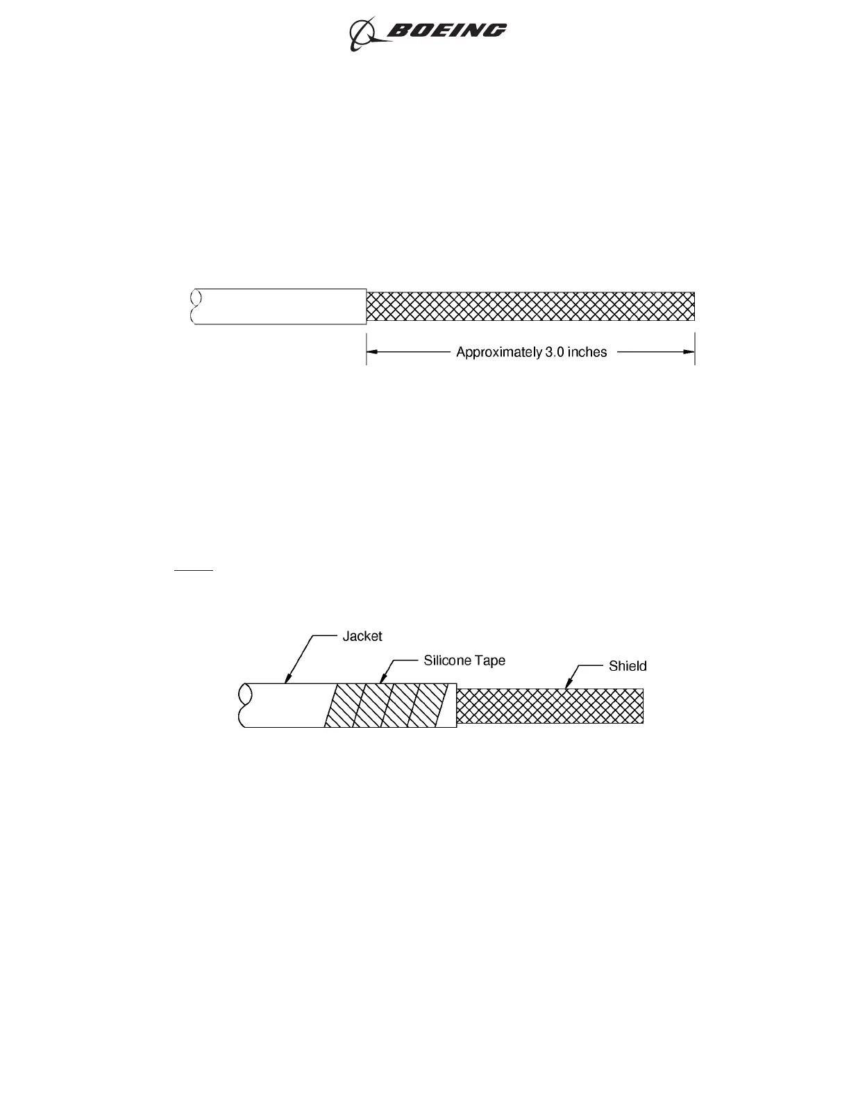
(2) Remove approximately 3 inches of the outer jacket from the end of the wire on each side of the
repair location.
Refer to:
• Figure 210
• Subject 20-00-15 for the outer jacket removal procedures.
(3) Wrap a minimum of one layer of Temperature Grade D Type I silicone tape on each side of the
repair location on the each cable jacket near the end of the jacket where the shield termination
ring will be located.
Refer to Figure 212 and Figure 211.
NOTE: Additional wraps of silicone tape tape may be necessary on the jacket to give a proper fit
for the shield termination ring.
(4) Put a shield termination ring on the jacket of the wire on each side of the repair location. Refer to
Figure 211.
Make sure that the distance from the end of the jacket to the forward edge of the shield terminator
band is approximately 0.25 inch.
SHIELDED WIRE PREPARATION
Figure 210
POSITION OF THE SILICONE TAPE ON THE JACKET OF THE SHIELDED WIRE
Figure 211
ASSEMBLY OF SPLICES
707, 727-787
STANDARD WIRING PRACTICES MANUAL
20-30-12
Page 251
Jun 15/2021D6-54446
ECCN 9E991 BOEING PROPRIETARY - See title page for details