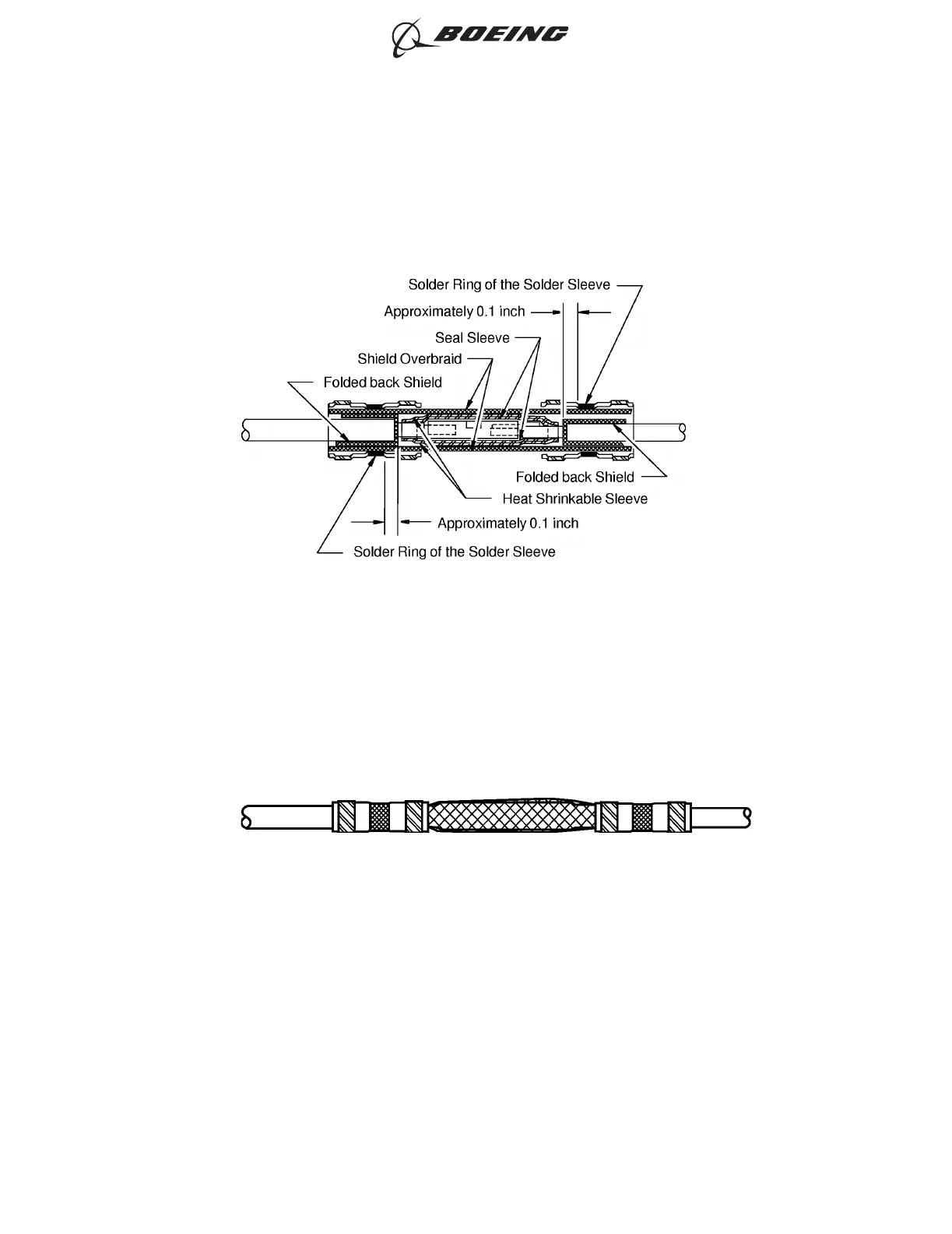
• The solder ring is on the shield overbraid and on the folded back shield of the cable
• The distance from the edge of the solder ring to the end of the shield overbraid is
approximately 0.1 inch.
(19) Apply heat to each solder sleeve until the solder flows into the shield overbraid and into the folded
back shield of each shielded wire. Refer to Figure 276.
(20) If it is necessary, remove the unwanted length of the shields that extend farther than the far ends
of the solder sleeves.
(21) Put the 4 inch length of 1/2 inch diameter heat shrinkable sleeve on the splice assembly.
(22) Shrink the sleeve into its position. Refer to Figure 277.
POSITION OF THE SOLDER RINGS OF THE SOLDER SLEEVES AND THE SHIELDS
Figure 275
POSITION OF THE SOLDER SLEEVES AND THE SHIELD OVERBRAID
Figure 276
ASSEMBLY OF SPLICES
707, 727-787
STANDARD WIRING PRACTICES MANUAL
20-30-12
Page 301
Jun 15/2021D6-54446
ECCN 9E991 BOEING PROPRIETARY - See title page for details