Make sure that:
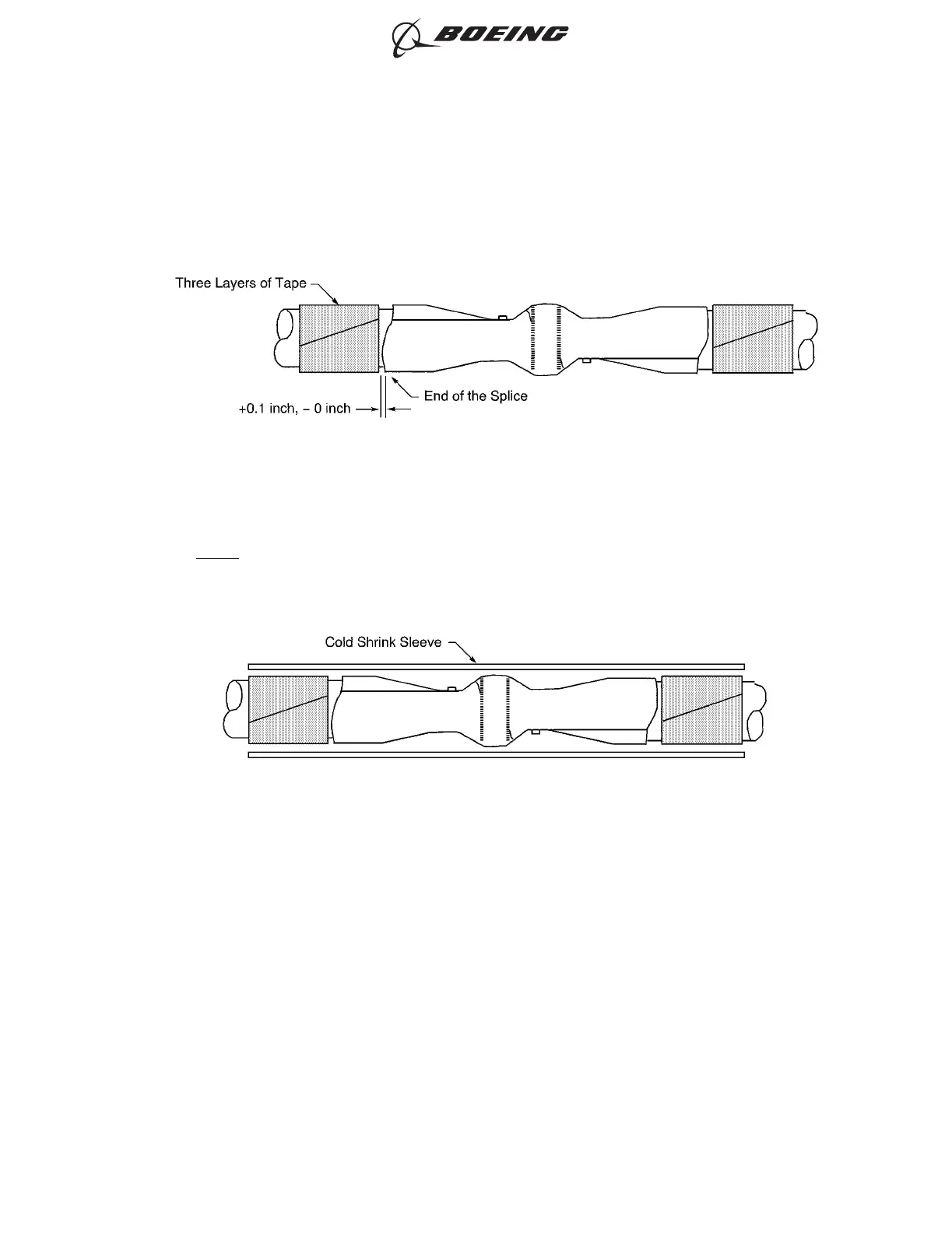
• The end of the layer of tape is a maximum of 0.1 inch from the end of the splice
• The layers of tape do not make an overlap with the splice
• The layers of tape have 100 percent overlap.
(6) Install the cold shrink sleeve. Refer to Figure 24.
NOTE: If the specified cold shrink sleeve is not available, the a satisfactory alternative insulation
is to install two layers of self-bonding silicone tape and wire harness ties. Refer to Step
4.K.(7).
(a) Align the center of the sleeve with the center of the splice.
(b) Hold the sleeve in its position.
(c) Pull the core of the sleeve in the direction that is parallel to the longitudinal axis of the
sleeve until the core is fully removed.
(d) Examine the cold shrink sleeve for a tight fit on the splice.
(e) If the cold shrink sleeve does not make a tight fit, assemble a wire harness tie approximately
0.5 inch from each end of the sleeve.
Refer to Subject 20-10-11 for the procedure to assemble a wire harness tie.
Make sure that the lacing tape is a Temperature Grade D material.
POSITION OF THE LAYERS OF TAPE ON THE WIRE
Figure 23
INSULATION OF THE SPLICE WITH A COLD SHRINKABLE SLEEVE
Figure 24
ASSEMBLY AND REPAIR OF THE AMP AND BACS52N COPALUM SPLICES
707, 727-787
STANDARD WIRING PRACTICES MANUAL
20-30-13
Page 34
Oct 15/2015D6-54446
ECCN 9E991 BOEING PROPRIETARY - See title page for details