Table 20 BACS52N SPLICES THAT MUST HAVE LAYERS OF BUILDUP TAPE (Continued)
Splice
Wire Size(AWG)
Layers of Tape
First Splice End Second Splice End
BACS52N-5A78 1/0 2 0
BACS52N-6
2/0 1/0 0
1/0 1/0 0
BACS52N-6A78 2/0 1/0 0
BACS52N-7 3/0 2/0 0
BACS52N-7A78 3/0 2/0 0
BACS52N-8 4/0 3/0 0
BACS52N-8A78 4/0 3/0 0
(1) Make a selection of a solvent from Table 7.
(2) With a clean wiper and solvent, clean the splice and a minimum of two inches of the wire from
each end of the splice.
(3) Dry the clean area with a clean wiper.
(4) Find if layers of tape are necessary to fill the area between the cold shrink sleeve and the wire
insulation. Refer to Table 19 for AMP splices and Table 20 for BACS52N splices.
(5) If layers of buildup tape are necessary to fill the area between the cold shrink sleeve and the wire
insulation, install a minimum of three layers of tape on the wire insulation.
(a) Make a selection of an insulation tape from Table 7.
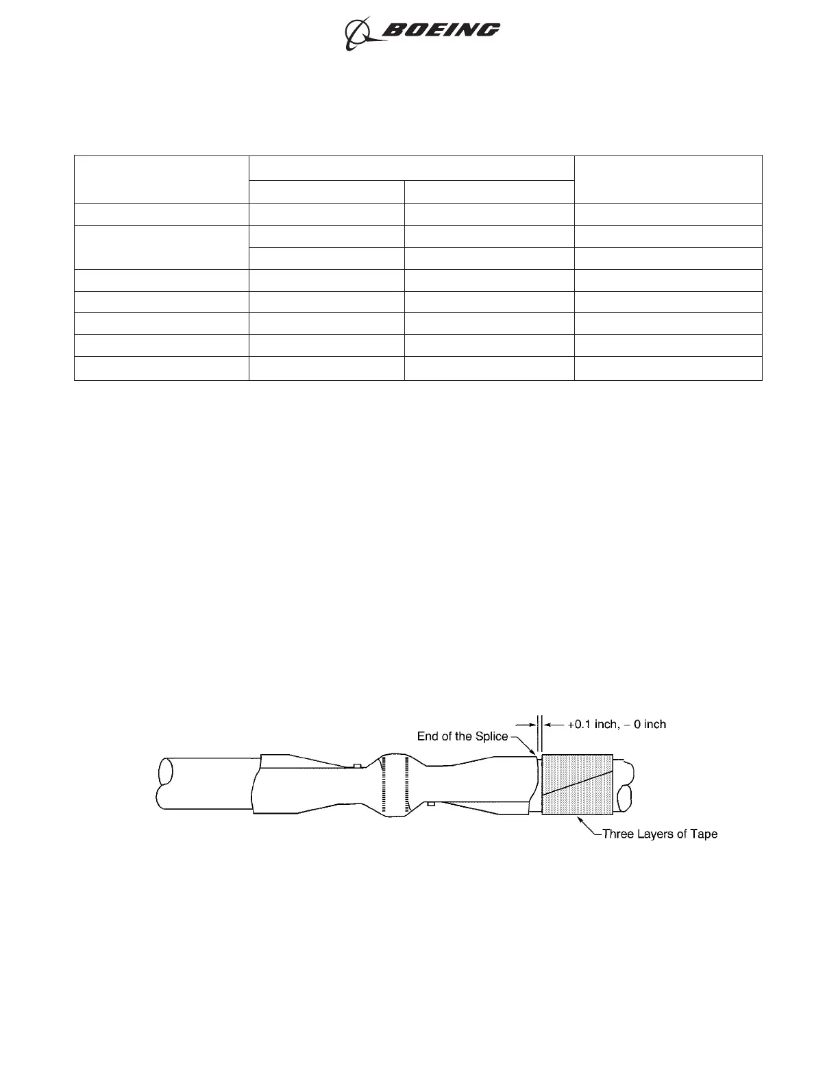
(b) Wind three layers of tape on the wire insulation at one end of the splice. Refer to Figure 22.
Make sure that:
• The end of the layer of tape is a maximum of 0.1 inch from the end of the splice
• The layers of tape do not make an overlap with the splice
• The layers of tape have 100 percent overlap.
(c) Wind three layers of tape on the wire insulation at the other end of the splice. Refer to
Figure 23.
POSITION OF THE LAYERS OF TAPE ON THE WIRE
Figure 22
ASSEMBLY AND REPAIR OF THE AMP AND BACS52N COPALUM SPLICES
707, 727-787
STANDARD WIRING PRACTICES MANUAL
20-30-13
Page 33
Oct 15/2015D6-54446
ECCN 9E991 BOEING PROPRIETARY - See title page for details