(d) Hold the sleeve in position.
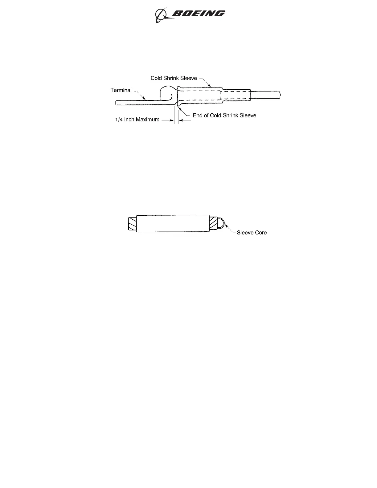
(e) Pull the sleeve core out from the rear end of the sleeve. Refer to Figure 39.
(3) If a 0.5 inch wide Type I silicone tape is specified, put two layers of the tape on the transition
barrel of the terminal lug. Refer to Figure 40.
Make sure that:
• The forward end of each layer is aligned with the forward end of the transition barrel
• The rear end of each layer extends 0.5 inch minimum rearward from the rear end of the
tongue of the terminal lug
• Each layer makes a 50 percent overlap with itself
• The second layer of tape is wound in the opposite direction of the first layer
• The layers of tape do not make an overlap with the bottom surface of the tongue of the
terminal lug.
POSITION OF THE COLD SHRINK SLEEVE ON THE TERMINAL ASSEMBLY
Figure 38
LOCATION OF THE SLEEVE CORE
Figure 39
ASSEMBLY OF AMP (TYCO) COPALUM, MS25435 AND THOMAS & BETTS ALUMINUM
TERMINALS
707, 727-787
STANDARD WIRING PRACTICES MANUAL
20-30-14
Page 46
Oct 15/2017D6-54446
ECCN 9E991 BOEING PROPRIETARY - See title page for details