Using iView
8-28 Manual # 42-02-7223
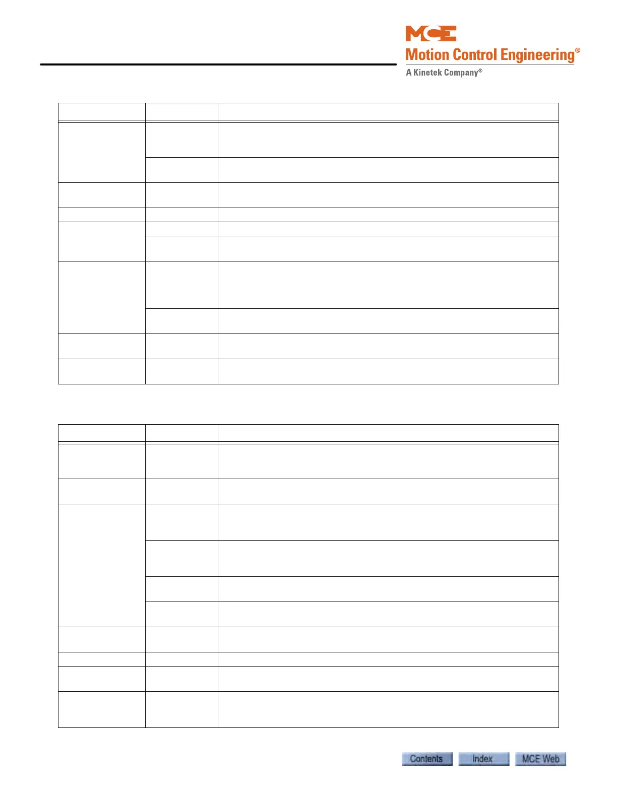
I/O Board Configuration Graphical display and organization of controller and cartop I/O boards
including specific input and output assignment on connectors
(see page 9-122).
Configurable
outputs
Determines during which modes of operation the Door Enable Output,
Automatic Closing Output and/or Hall Door Button Output are disabled.
IBox
Configuration
IP information for iControl (see page 9-148).
Load Weigher Load Weigher configuration and threshold settings (see page 9-149).
Motor Field Control Motor Field operation, calibration, voltage, and PID settings
Configuration Voltage, Output timer, and Current reference settings across motor out-
put range in increments of 10% (fine tuning) (see page 9-151).
Pattern Common Display and edit parameters common to all pattern profiles. Position
encoder resolution, leveling and releveling speeds, pattern scaling, dead
zone distance, door pre-opening distance, and position synchronization by
floor or terminal switches (see page 9-154).
Modes Parameter settings for Standard, Earthquake, Emergency power, Emer-
gency slowdown, Correction, Inspection, and Alternate 1-2 profiles.
Terminal
Switches
Position margin settings for up and down normal terminal and emergency
terminal switches, and Overspeed 1 margin setting (see page 9-160).
Timer Tables Programming of timed operations (Sabbath, Swing and Auto stop opera-
tion).(see page 9-161).
Table 8.6 Controller - Diagnostics Tabs
Tab Sub-Tab Content
Operational
Status
Displays the car status including: motion, speed, position, pattern, motor
and brake, processor, in-service, leveling, door locks, faults and car status
(see page 9-7).
Data Trap Use this tool to record and analyze controller data including input and
output states, internal flags and parameter values (see page 9-12).
Diagnostic
Flags
Car Operation Displays status of car operation input and output flags, including front and
rear doors, e.g. car call above, car call below. Click arrow buttons to dis-
play dependent outputs (see page 9-13).
Motion Displays the status of Passenger (automatic) and Inspection mode motion
related inputs and outputs, e.g. Ready, Synchronization and Qualifier sta-
tus.
Drive Displays the status of Drive related inputs and outputs, e.g. Up direction
request, Pattern enable, and Motor run mode.
Safety Displays the status of Safety related inputs and outputs, e.g. Car top exit
open, Governor open, and Safety (Car) open.
Diagnostic
Outputs
Selection and display of up to sixteen system outputs for monitoring or
diagnosis. Hundreds of outputs are available (see page 9-14).
Event Log Display of recorded controller events (see page 9-15).
Fault Bypass Enable/disable selected system faults to facilitate adjustment and testing.
Display of faults currently bypassed (see page 9-18).
Terminal
Switches Status
Displays the learned terminal switch speeds and positions, overspeed and
position fault thresholds and last pass positions and speeds
(see page 9-20).
Table 8.5 Controller - Configuration Tabs
Tab Sub-Tab Content