336 www.xilinx.com Virtex-5 FPGA User Guide
UG190 (v5.0) June 19, 2009
Chapter 7: SelectIO Logic Resources
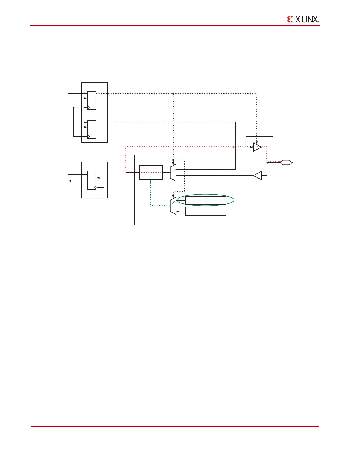
The second case uses bidirectional IODELAY when the I/O is an input switching to an
output. Figure 7-13 shows the IOB and IODELAY moving toward the output mode as set
by the 3-state TSCONTROL signal coming from the ODDR T flip-flop. This controls the
selection of MUXes E and F for the output path and ODELAY_VALUE respectively.
Additionally, the OBUF changes to not being 3-stated and starts to drive the PAD.
X-Ref Target - Figure 7-13
Figure 7-13: IODELAY and IOB in Output Mode when 3-state is Enabled
IODELAY_04_082107
IOB
IODELAY
T
Q1
Q2
T2
CLK
CLK
MUX E
Delay
Chain
ODATAIN
IDATAIN
MUX F
OBUF
PA D
IBUF
D1
T1
D2
ODELAY_VALUE
IDELAY_VALUE
ODDR
TSCONTROL
ODATAIN
DATAOUT
ODDR
IDDR
 Loading...


