70 www.xilinx.com Virtex-5 FPGA User Guide
UG190 (v5.0) June 19, 2009
Chapter 2: Clock Management Technology
• If PERIODCLKIN = FINE_SHIFT_RANGE, then the PHASE_SHIFT in variable-
positive mode is limited to +255. In fixed and variable-center mode the
PHASE_SHIFT is limited to ±255.
• If PERIODCLKIN ≤FINE_SHIFT_RANGE, then the PHASE_SHIFT in variable-
positive mode is limited to +255. In fixed and variable-center mode the
PHASE_SHIFT is limited to ±255.
• For all previously described cases, the direct mode is always limited to +1023.
If the phase shift is limited by the FINE_SHIFT_RANGE, use the coarse-grained phase
shift to extend the phase-shift range or set DCM_PERFORMANCE_MODE attribute to
MAX_RANGE to increase the FINE_SHIFT_RANGE. Figure 2-5 illustrates using CLK90,
CLK180, and CLK270 outputs assuming FINE_SHIFT_RANGE = 10 ns.
In variable mode, the phase-shift factor is changed by activating PSEN for one period of
PSCLK. At the PSCLK clock cycle where PSEN is activated, the level of PSINCDEC input
determines whether the phase-shift increases or decreases. A High on PSINCDEC
increases the phase shift, and a Low decreases the phase shift.
After the deskew circuit increments or decrements, the signal PSDONE is asserted High
for a single PSCLK cycle. This allows the next change to be performed.
The user interface and the physical implementation are different. The user interface
describes the phase shift as a fraction of the clock period (N/256). The physical
implementation adds the appropriate number of buffer stages (each DCM_TAP) to the
clock delay. The DCM_TAP granularity limits the phase resolution at higher clock
frequencies.
All phase-shift modes, with the exception of DIRECT mode, are temperature and voltage
adjusted. Hence, a V
CC
or temperature adjustment does not change the phase shift. The
DIRECT phase shift is not temperature or voltage adjusted since it directly controls
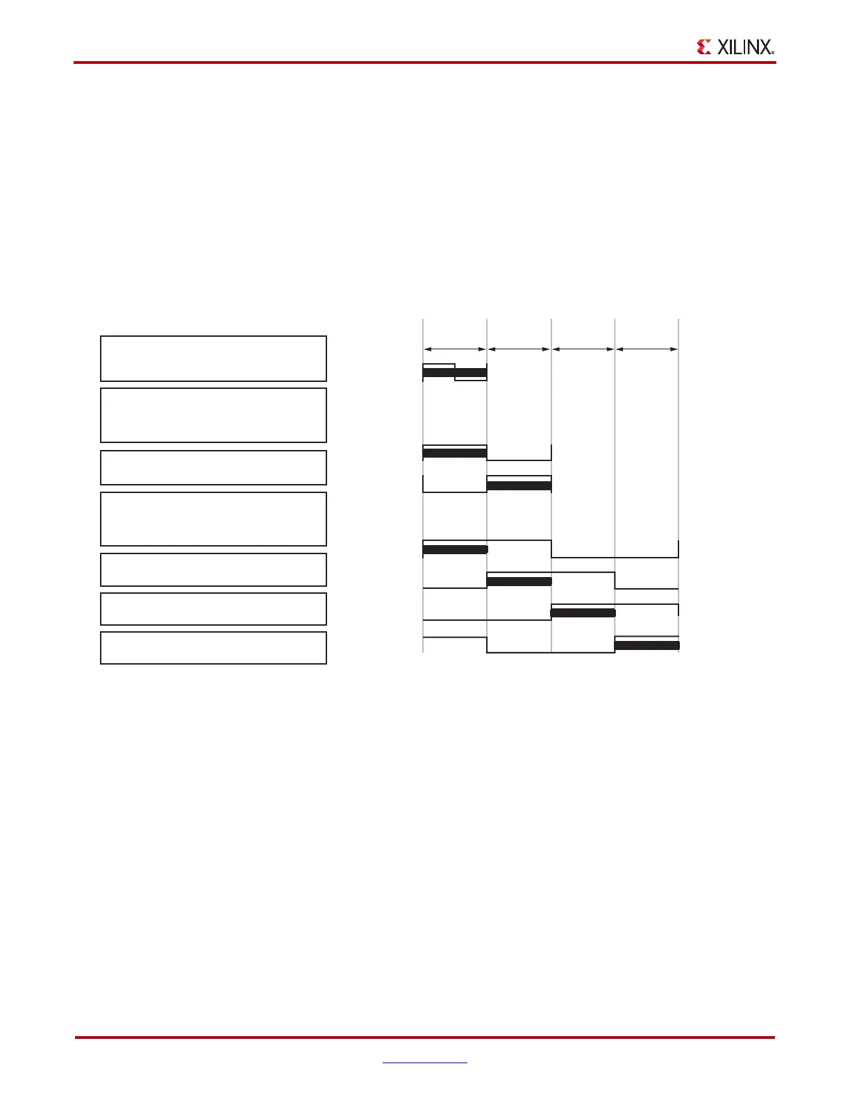
X-Ref Target - Figure 2-5
Figure 2-5: Fixed Phase-Shift Examples
For frequency ≥ 100 MHz (period ≤ 10 ns)
CLK0 PHASE_SHIFT = 0 - 255 covers the
whole range of period.
For frequency between 50 - 100 MHz
(period 10 - 20 ns). At 50 MHz, use
CLK0 PHASE_SHIFT= 0 - 127 for the
first 10 ns.
Use CLK180 with PHASE_SHIFT= 0 - 127
for the next 10 ns.
For frequency between 25 - 50 MHz
(period 20 - 40 ns). At 25 MHz, use
CLK0 PHASE_SHIFT= 0 - 63 for the
first 10 ns.
Use CLK90 with PHASE_SHIFT= 0 - 63
for the next 10 ns.
Use CLK180 with PHASE_SHIFT= 0 - 63
for the next 10 ns.
Use CLK270 with PHASE_SHIFT= 0 - 63
for the last 10 ns.
CLK0(100 MHz)
CLK0(50 MHz)
CLK180(50 MHz)
CLK0(25 MHz)
CLK90(25 MHz)
CLK180(25 MHz)
CLK270(25 MHz)
10 ns 10 ns 10 ns 10 ns
ug0190_2_05_032506
 Loading...


