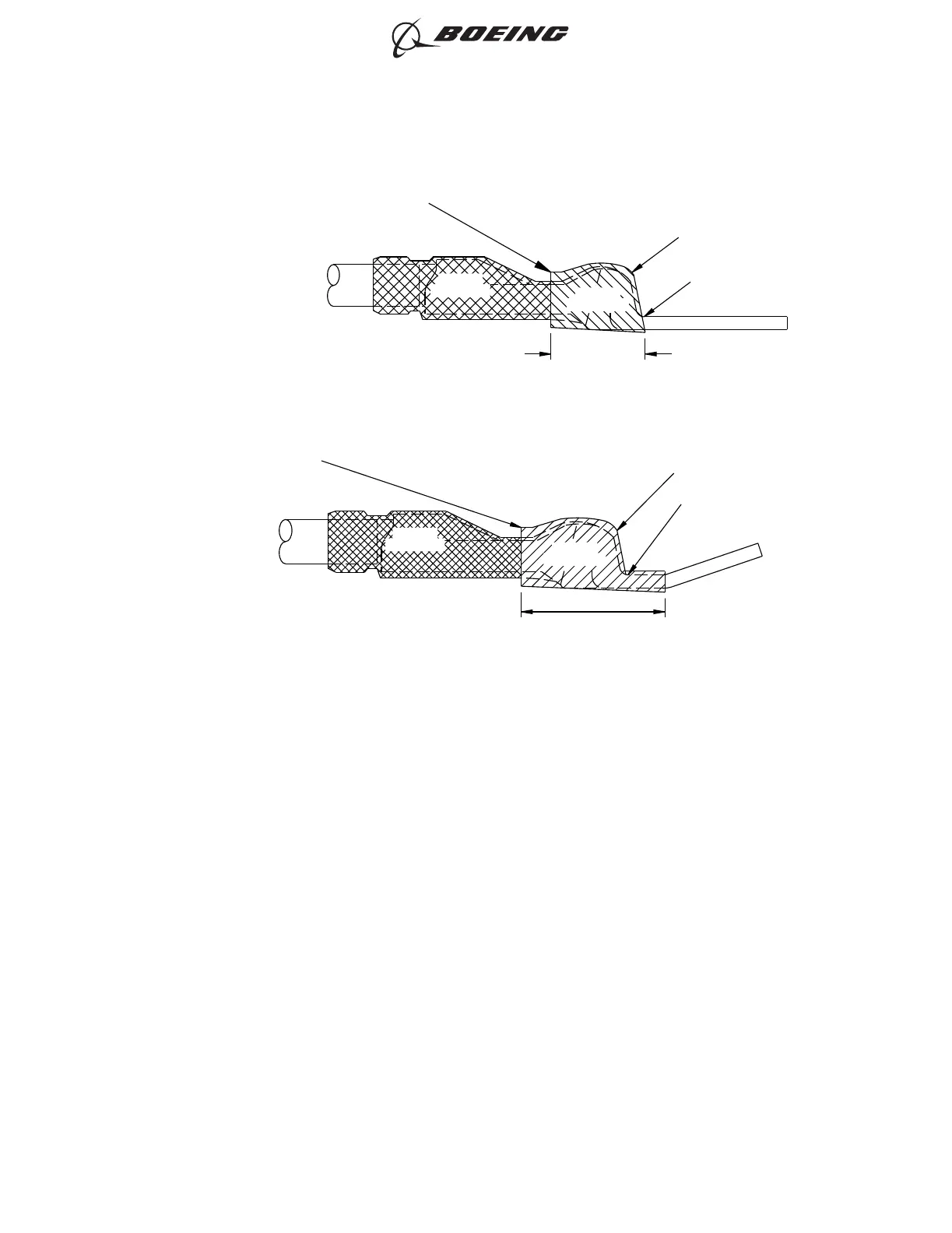
1) Figure 3 and Figure 4 Figure 6 for 30° bent terminals.
2) Put two layers of the 0.5 inch A-A-59163 on the transition barrel of the terminal lug. End
approximately as shown.
a) Refer to
<1> Figure 3.
<2> Figure 4.
3) Align the forward end of each layer with the forward end of the transition barrel.
4) Extend the rear end of each layer a minimum of 0.5 inch rearward from the transition barrel.
5) Overlap each layer with itself by approximately 50%.
6) Wind the second layer of tape in the opposite direction of the first layer.
7) Overlap the layers of tape with the bottom surface of the tongue of the terminal lug.
(g) Install the phase identification sleeve in accordance with Subject 20-10-14, Figure 5 and
Figure 6. Make sure that the phase identification sleeve does not overlap the rear edge of
the terminal lug.
ZONE C
(A-A 59163)
ZONE B
(BACT63E)
FORWARD END OF
TRANSITION BARREL
TWO LAYERS OF 0.5 WIDE
A-A-59163 TAPE
1.00-1.25 INCH
THIS EDGE OF THE TAPE IS
UNDEFINED. STRAIGHT LINE
SHOWN ONLY FOR PURPOSE
OF ILLUSTRATION.
2529439 S0000598153_V1
Installation of A-A 59163 Tape for Straight Generator Terminals
Figure 3
ZONE C
(A-A 59163)
ZONE B
(BACT63E)
SILICONE TAPE
FORWARD END OF
TRANSITION BARREL
STRAIGHT LINE
SHOWN ONLY
FOR PURPOSE OF
ILLUSTRATION
1.50 TO 1.75 INCHES
2529445 S0000598154_V1
Installation of A-A 59163 Tape for 30° Bent Generator Terminals
Figure 4
ASSEMBLY OF TE/AMP NICKEL PLATED COPALUM TERMNAL LUGS
707, 727-787
STANDARD WIRING PRACTICES MANUAL
20-30-23
Page 7
Feb 15/2021D6-54446
ECCN 9E991 BOEING PROPRIETARY - See title page for details



 To Next Page