• Subject 20-00-15 for the insulation removal procedures
Make sure that:
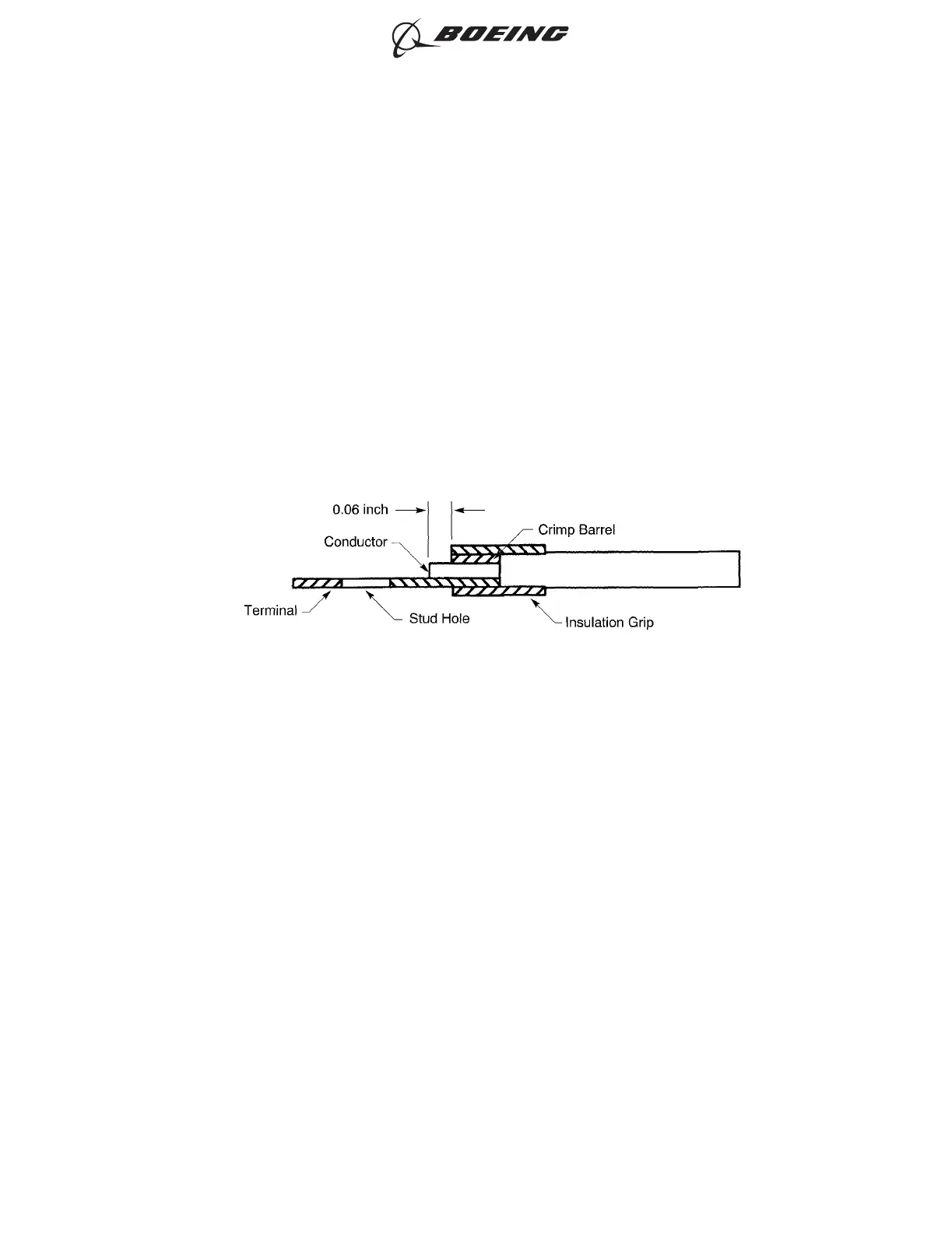
• When the wire is in the terminal lug, the end of the conductor extends 0.06 ± 0.03 inch
farther than the end of the crimp barrel
• The clearance from the end of the conductor is sufficent for the installation of the washer
and the nut
• The maximum distance from the end of the wire insulation of a single wire to the end of the
crimp barrel is 0.12 inch for AWG 10 and smaller, and 0.25 inch for AWG 8 and larger
• The conductor does not have nicked or cut strands
• If the insulation is removed by the application of heat, the conductor has not moved from the
center of the wire
• If the insulation is removed by the application of heat, the remaining insulation does not
have blisters or evidence of overheating
• The remaining insulation is not frayed.
(5) For a terminal lug in a high temperature area or in a high vibration area, if a heat gun can be
used, put a 1.00 inch ±0.06 inch length of TFE-2X heat shrinkable sleeve on the wire.
Make sure that the sleeve has the smallest diameter that will let the sleeve move easily on the
wire and on the crimp barrel of the terminal.
(6) Put the conductor of the wire in the crimp barrel of the terminal lug. Refer to Figure 22.
Make sure that:
• All of the strands of the conductor are in the crimp barrel
• The end of the conductor extends 0.06 ± 0.03 inch farther than the end of the crimp barrel
• If the terminal lug has an insulation grip, the end of the wire insulation is in the insulation
grip of the terminal lug
• If the terminal lug does not have an insulation grip, the maximum distance from the end of
the wire insulation of a single wire to the end of the crimp barrel is 0.12 inch for AWG 10 and
smaller, and 0.25 inch for AWG 8 and larger
• If a sleeve is on the wire, the sleeve does not go into the crimp barrel of the terminal lug
• The clearance from the end of the conductor is sufficent for the installation of the washer
and the nut.
INSULATION REMOVAL LENGTH
Figure 22
ASSEMBLY OF INSULATED AND UNINSULATED TERMINAL LUGS
707, 727-787
STANDARD WIRING PRACTICES MANUAL
20-30-11
Page 72
Feb 15/2020D6-54446
ECCN 9E991 BOEING PROPRIETARY - See title page for details