Refer to:
• Figure 7 for the ferrule size
• Table 34 for the Temperature Grade
• Table 35 for the ferrule part numbers.
Make sure that:
• The inner ferrule is the smallest ferrule that can move freely on the two outer jackets
• The outer ferrule is the smallest ferrule that can move freely on the shields, the shield
sleeve material, and the inner ferrule.
(3) Make a selection of a ferrule crimp tool from Table 47.
(4) Make a selection of a Temperature Grade B or higher insulation tape from Table 52.
Make sure that the tape has a width of 0.5 inch minimum to 1.0 inch maximum.
(5) Make a selection of a Temperature Grade B or higher heat shrinkable sleeve from Table 51.
NOTE: For alternative heat shrinkable sleeves, refer to Subject 20-00-11.
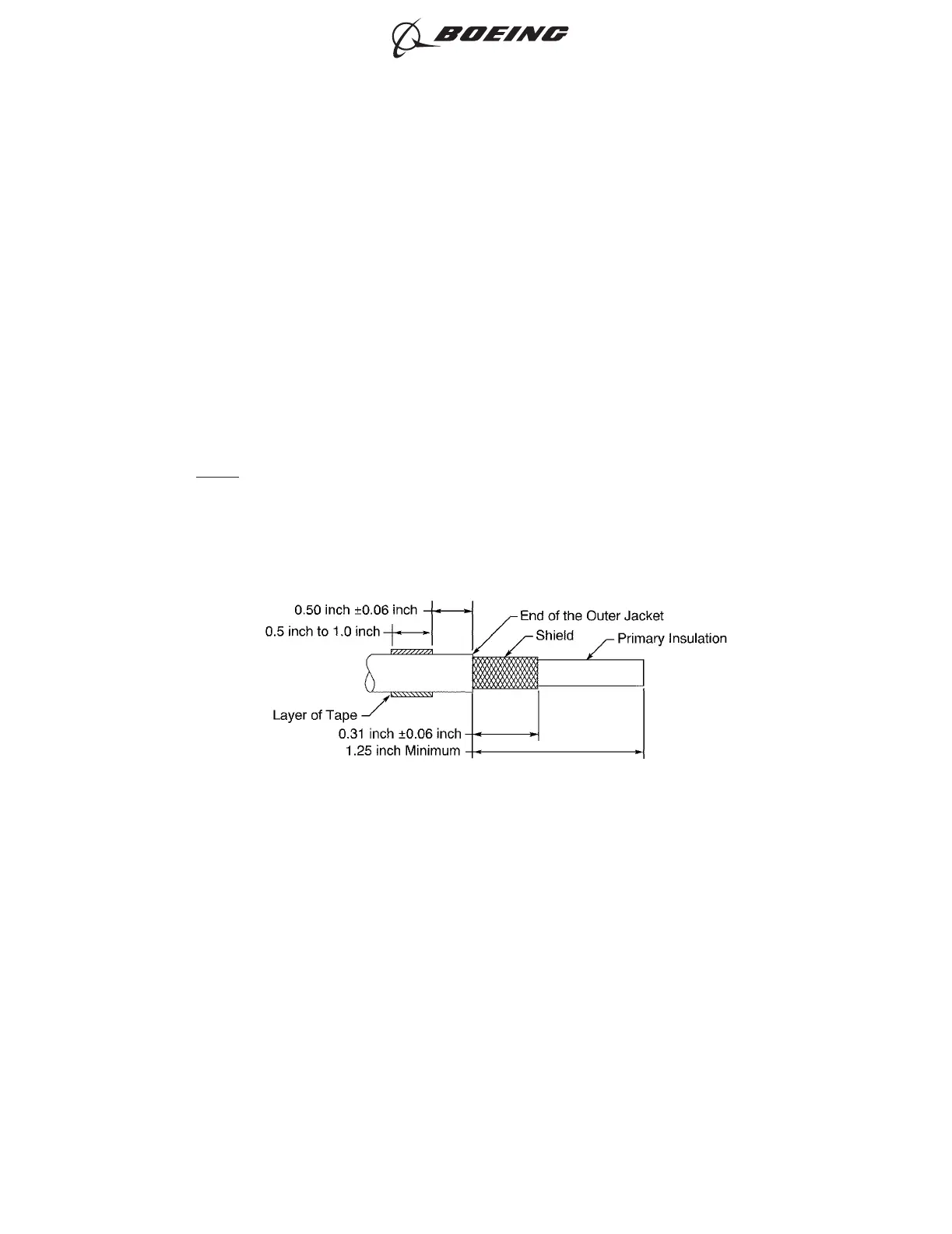
(6) Prepare each end of the shielded wires.
Refer to:
• Figure 161
• Subject 20-00-15 for the outer jacket removal procedures.
(a) Remove a 1.25 inch minimum length of the outer jacket from the end of the wire.
(b) Remove the necessary length of the shield from the end of the wire.
Make sure that the remaining shield is 0.31 inch ±0.06 inch.
(c) Wind a layer of the insulation tape on the outer jacket of each wire 0.50 inch ±0.06 inch
farther than the end of the outer jackets.
Make sure that:
• The tape goes around the circumference of the wire a minimum of two times
• The tape makes a 100 percent overlap.
(7) Cut the necessary length of the sleeve.
SHIELDED WIRE PREPARATION
Figure 161
ASSEMBLY OF SPLICES
707, 727-787
STANDARD WIRING PRACTICES MANUAL
20-30-12
Page 192
Jun 15/2021D6-54446
ECCN 9E991 BOEING PROPRIETARY - See title page for details