Make sure that the sleeve extends a minimum of 1.5 inches farther than the rear end of the
ferrules on each end of the shield splice.
(8) Cut the necessary length of the shield sleeve material.
Make sure that the ends of the shield sleeve material extend farther than the rear end of the
ferrules on each end of the shield splice.
(9) Put these components on the end of one pair of shielded wires:
• The sleeve
• The outer ferrule
• The inner ferrule.
(10) Put these components on the end of the other pair of shielded wires:
• The outer ferrule
• The inner ferrule
• The shield sleeve material.
NOTE: If it is necessary, the strands at the end of the shield sleeve material can be moved apart
to make it easier to put the shield sleeve material on the wire.
(11) Make a selection of an applicable Temperature Grade B conductor splice configuration for two
wires to two wires. Refer to Paragraph 9.A.
(12) Assemble the conductor splice. Refer to the applicable procedure given in Paragraph 9.A.
(13) Assemble the end of the shield splice opposite the end with the shield sleeve material.
(a) Move the outer ferrule on the shield sleeve material.
(b) Move the strands of the shields apart and make them straight.
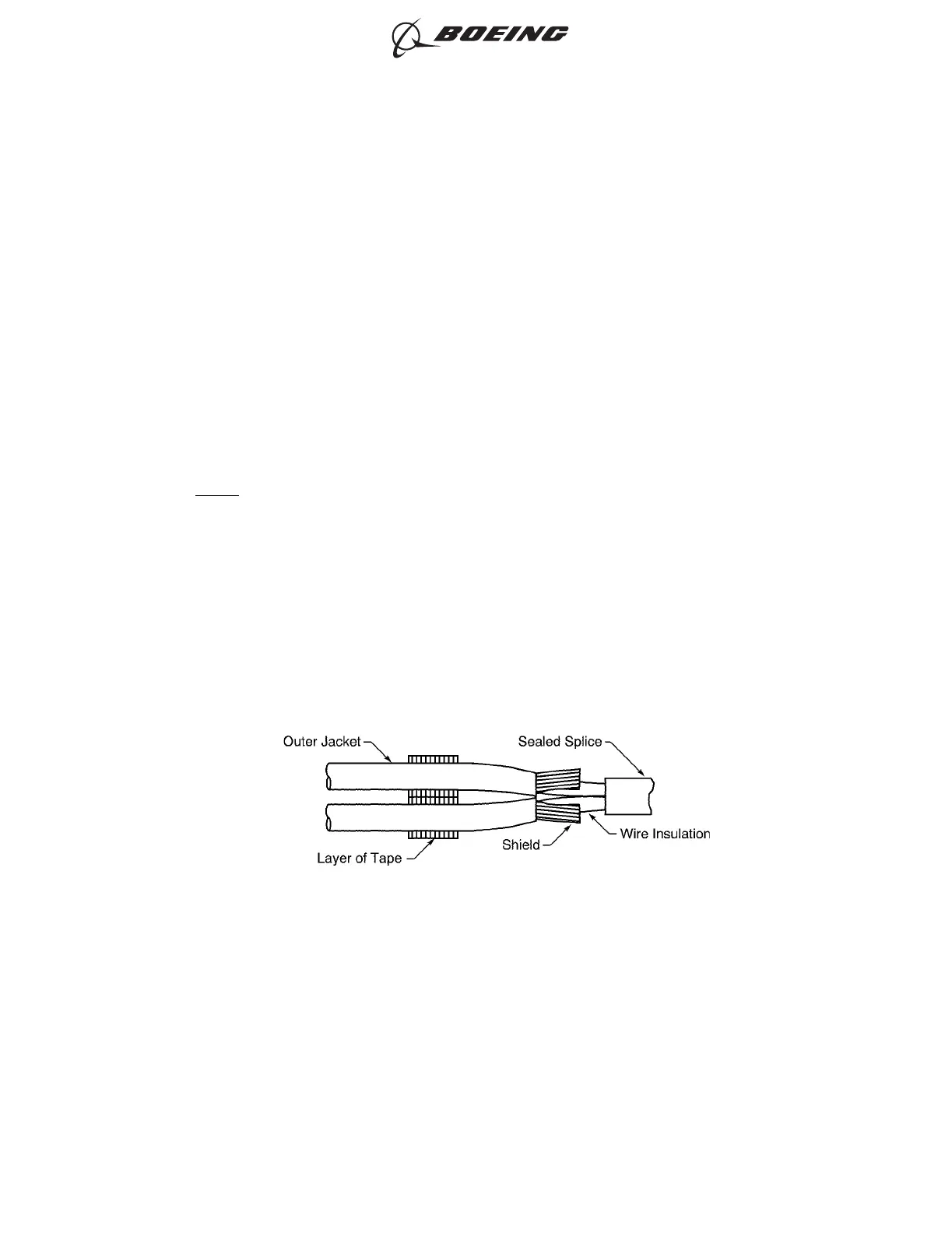
(c) Move the strands of each shield away from the adjacent wire. Refer to Figure 162.
(d) Align the forward end of the inner ferrule with each end of the outer jackets.
(e) Fold the strands of the shields back on the inner ferrule to make the strands of the shield
symmetrical around the circumference of the ferrule.
(f) Align the end of the shield sleeve material with the end of the strands of the shields that are
folded back.
POSITION OF THE SHIELDS
Figure 162
ASSEMBLY OF SPLICES
707, 727-787
STANDARD WIRING PRACTICES MANUAL
20-30-12
Page 193
Jun 15/2021D6-54446
ECCN 9E991 BOEING PROPRIETARY - See title page for details