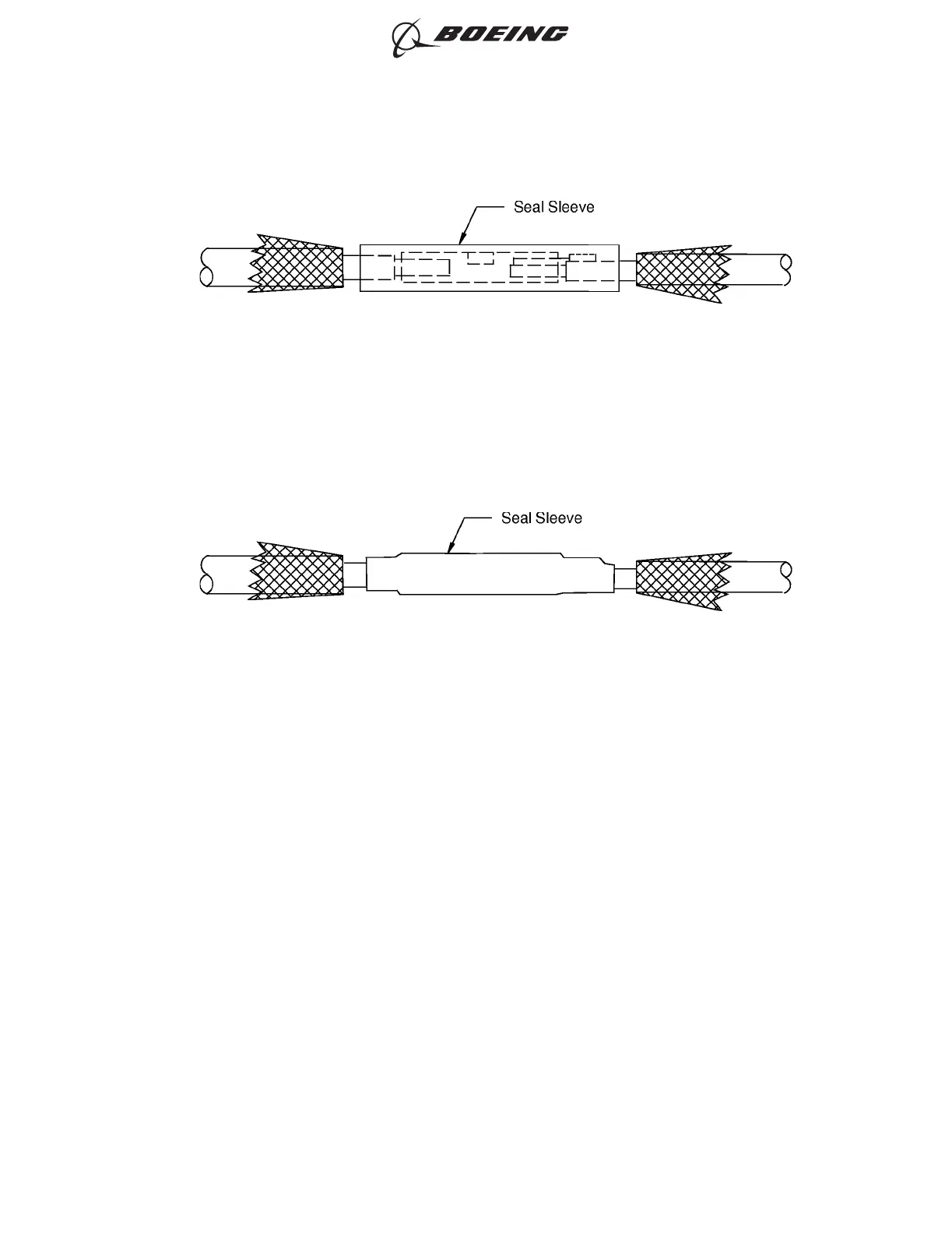
(14) Shrink the seal sleeve into its position. Refer to Figure 271.
Make sure that the seal sleeve is on the splice and on the end of the filler wire.
(15) Put the 2 inch length of 1/4 inch diameter heat shrinkable sleeve from the 10 AWG wire on the
seal sleeve.
(16) Shrink the 1/4 inch diameter sleeve into its position. Refer to Figure 272.
Make sure that:
• The sleeve is on the seal sleeve
• The center of the sleeve is located at the center of the seal sleeve
• The ends of the sleeve are not on the folded back shields of the wires.
INITIAL POSITION OF THE SEAL SLEEVE ON THE SPLICE
Figure 270
POSITION OF THE SEAL SLEEVE
Figure 271
ASSEMBLY OF SPLICES
707, 727-787
STANDARD WIRING PRACTICES MANUAL
20-30-12
Page 299
Jun 15/2021D6-54446
ECCN 9E991 BOEING PROPRIETARY - See title page for details