Refer to Figure 269:
(5) Fold back 0.5 inch ±0.06 inch of the shield on the 10 AWG wire.
(6) Fold back 0.5 inch ±0.06 inch of the shield on the 16 AWG wire.
(7) Put the conductor of the 10 AWG wire in the crimp barrel of one end of the NAS1387-6 wire splice
from the D-150-0272 splice kit.
(8) Make a selection of a crimp tool from Table 44 for a size 12-10 crimp barrel for the NAS1387-6
splice.
(9) Crimp the end of the splice that has the 10 AWG wire.
(10) Put the conductor of the 16 AWG wire and the conductor of the 18 AWG filler wire in the crimp
barrel of the other end of the splice.
(11) Crimp the end of the splice that has the 16 AWG conductor and the 18 AWG filler wire conductor.
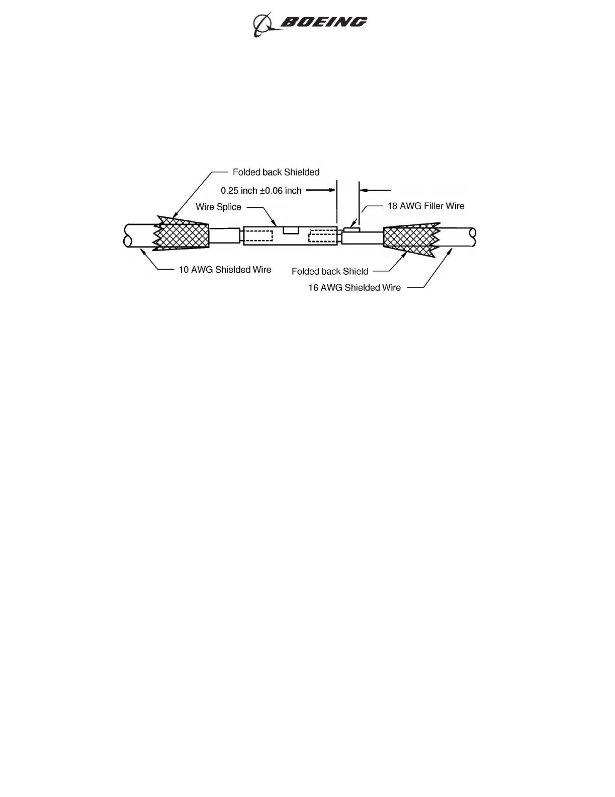
(12) Remove the unwanted length of the 18 AWG filler wire. Refer to Figure 269.
Make sure that the distance from the end of the filler wire to the end of the crimp barrel of the
splice is 0.25 inch ±0.06 inch.
(13) Put the seal sleeve from the 16 AWG wire on the splice and on the filler wire. Refer to Figure 270.
POSITION OF THE CONDUCTORS IN THE SPLICE
Figure 269
ASSEMBLY OF SPLICES
707, 727-787
STANDARD WIRING PRACTICES MANUAL
20-30-12
Page 298
Jun 15/2021D6-54446
ECCN 9E991 BOEING PROPRIETARY - See title page for details