xvi Figures
Figure 25 9U Expansion Module Fiducial Location . . . . . . . . . . . . . . . . . . . . . . . . . . . . . . . . . . . . 191
Figure 26 5U Control Module Column Location . . . . . . . . . . . . . . . . . . . . . . . . . . . . . . . . . . . . . . . 192
Figure 27 9UExpansion Module Column Location . . . . . . . . . . . . . . . . . . . . . . . . . . . . . . . . . . . . 192
Figure 28 Location of Blade LEDs . . . . . . . . . . . . . . . . . . . . . . . . . . . . . . . . . . . . . . . . . . . . . . . . . 428
Figure 29 Location of Tape Drive LEDs . . . . . . . . . . . . . . . . . . . . . . . . . . . . . . . . . . . . . . . . . . . . . 431
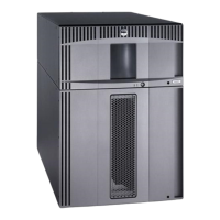
Figure 30 ML6020, Front View . . . . . . . . . . . . . . . . . . . . . . . . . . . . . . . . . . . . . . . . . . . . . . . . . . . 436
Figure 31 Library, Front View Showing Front Bezels . . . . . . . . . . . . . . . . . . . . . . . . . . . . . . . . . . 437
Figure 32 ML6020, Rear View . . . . . . . . . . . . . . . . . . . . . . . . . . . . . . . . . . . . . . . . . . . . . . . . . . . . 438
Figure 33 5U Library Control Module, Front . . . . . . . . . . . . . . . . . . . . . . . . . . . . . . . . . . . . . . . . . 439
Figure 34 Library, Front View, I/E Station Door Open . . . . . . . . . . . . . . . . . . . . . . . . . . . . . . . . . . 439
Figure 35 Library Front View, Access Door, and I/E Station Door Open . . . . . . . . . . . . . . . . . . . . 440
Figure 36 I/E Station Lock Assembly . . . . . . . . . . . . . . . . . . . . . . . . . . . . . . . . . . . . . . . . . . . . . . . 440
Figure 37 I/E Station Slide Assembly (removed from module) . . . . . . . . . . . . . . . . . . . . . . . . . . . 441
Figure 38 Access Door, Inside (showing back of Operator Panel) . . . . . . . . . . . . . . . . . . . . . . . . 441
Figure 39 Operator Panel . . . . . . . . . . . . . . . . . . . . . . . . . . . . . . . . . . . . . . . . . . . . . . . . . . . . . . . 442
Figure 40 Model 1 Robot Assembly with Original Cable Spool . . . . . . . . . . . . . . . . . . . . . . . . . . . 443
Figure 41 Model 2 Robot Assembly (Picker Assembly and Y-Carriage Assembly) . . . . . . . . . . . . 444
Figure 42 Model 1 Picker Assembly . . . . . . . . . . . . . . . . . . . . . . . . . . . . . . . . . . . . . . . . . . . . . . . 445
Figure 43 Model 2 Picker Assembly . . . . . . . . . . . . . . . . . . . . . . . . . . . . . . . . . . . . . . . . . . . . . . . 445
Figure 44 Original Cable Spool. . . . . . . . . . . . . . . . . . . . . . . . . . . . . . . . . . . . . . . . . . . . . . . . . . . . 446
Figure 45 Cable Spool as of August 27, 2007 . . . . . . . . . . . . . . . . . . . . . . . . . . . . . . . . . . . . . . . . 447
Figure 46 Model 1 Parking Tab, Parked . . . . . . . . . . . . . . . . . . . . . . . . . . . . . . . . . . . . . . . . . . . . 448
Figure 47 Model 2 Parking Tab, Parked . . . . . . . . . . . . . . . . . . . . . . . . . . . . . . . . . . . . . . . . . . . . 448
Figure 48 Library Control Blade . . . . . . . . . . . . . . . . . . . . . . . . . . . . . . . . . . . . . . . . . . . . . . . . . . . 449
Figure 49 Power Supplies . . . . . . . . . . . . . . . . . . . . . . . . . . . . . . . . . . . . . . . . . . . . . . . . . . . . . . . 450
Figure 50 Power Supplies, Back View . . . . . . . . . . . . . . . . . . . . . . . . . . . . . . . . . . . . . . . . . . . . . . 451
Figure 51 Tape Drive, Front View . . . . . . . . . . . . . . . . . . . . . . . . . . . . . . . . . . . . . . . . . . . . . . . . . 452
Figure 52 Fibre Channel Tape Drive, Rear View . . . . . . . . . . . . . . . . . . . . . . . . . . . . . . . . . . . . . . 452
Figure 53 SCSI Tape Drive, Rear View . . . . . . . . . . . . . . . . . . . . . . . . . . . . . . . . . . . . . . . . . . . . . 452
Figure 54 Rack-mount Rails in Rack (as viewed from the front, showing studs installed in rack) . 456
Figure 55 Rack-mount Rails in Rack (as viewed from the back, showing studs installed in rack) 456
 Loading...


