432 Troubleshooting the Tape Library
Tape Drive FC Port Link LED
A Fibre Channel port link LED on a tape drive shows the current state of a Fibre Channel link and indicates
whether or not the link is ready to transmit commands.
The FC port link LED on a tape drive is located on the rear of the tape drive.
Use Table 15
to interpret Fibre Channel link activity on a tape drive:
Power Supply LEDs
RAS tickets typically report all problems related to power supplies. You can also observe the blinking pattern
of LEDs on power supplies to see if the they are functioning correctly.
Power supply LEDs indicate status by the rate at which they blink. The color of the LED identifies the area
of the component being reported.
Use Table 16
to interpret power supply activity.
In the RAS tickets associated with the defective power supply, record both the number of the module and
the number of the power supply connected to that module.
Each module can have up to two power supplies. The power supply on the left is #1, while the power supply
on the right is #2.
The 9U Expansion Modules are numbered according to their position in relation to the 5U Library Control
Module:
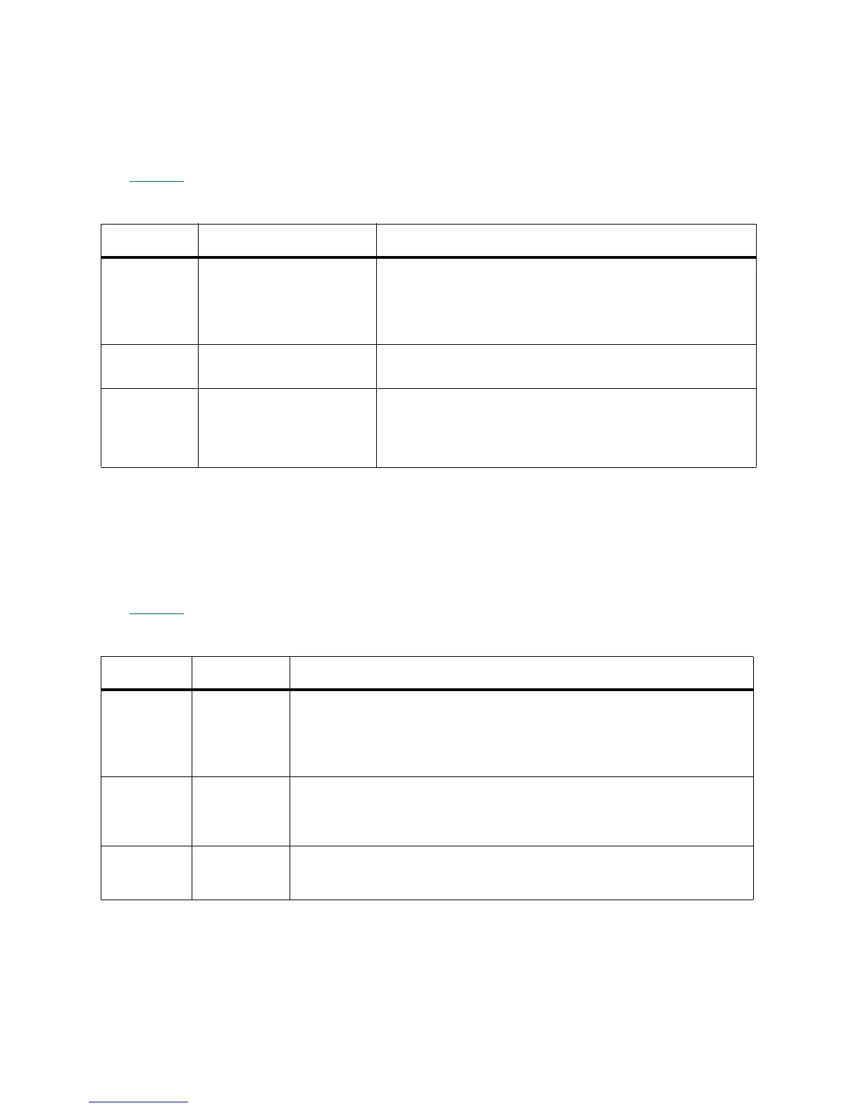
Table 15 Fibre Port Link LED on Tape Drive
LED Color Represents FC Port Link Status
Green Loop initialization protocol
(LIP) and activity
• Solid ON — Loop initialization protocol (LIP) has
occurred.
• Blinks at regular intervals — Host command/data activity
is occurring.
Amber Online and light detected • Solid ON — The library has enabled the tape drive data
bus, and it can detect light through a fiber optic cable.
No color No activity or no light
detected
• Solid OFF — Either the tape drive is off, or the tape drive
cannot detect light through a fiber optic cable (which is
equivalent to a missing FC cable). If the tape drive is
offline, the tape drive’s blue status LED will be solidly lit.
Table 16 Power Supply LEDs
LED Color Represents Power Supply Status
Green AC OK
(top)
• Solid ON — The power supply’s AC input is above the minimum
requirements to operate.
• Solid OFF — The power supply’s AC input is below the minimum
requirements to operate.
Green DC OK
(middle)
• Solid ON — The power supply’s output voltage is within regulation.
• Solid OFF — The power supply’s output voltage is not within
regulation.
Blue Standby
(bottom)
• Solid OFF — Normal.
• Solid ON — Swap mode: Ready to be removed or replaced.
 Loading...