(6) Remove any sharp edges from the terminal.
NOTE: The condition where the base metal of the terminal can be seen:
• Is not recommended
• Is permitted.
(7) Install the insulation sleeve. Refer to Paragraph 2.D..
D. Installation of the Insulation Sleeve on the Terminal Lug
Table 5
ASSEMBLY COMPONENTS
Component Type Part Number
Tape Silicone, Type I, 10 mil A-A-59163-1I0010-1.000
(1) If tape is specified in Table 3, make a selection of a tape from Table 5.
(2) Clean the terminal lug and a minimum of 2 inches of the wire insulation from the end of the crimp
barrel of the terminal lug.
(3) Dry the cleaned area with a wiper.
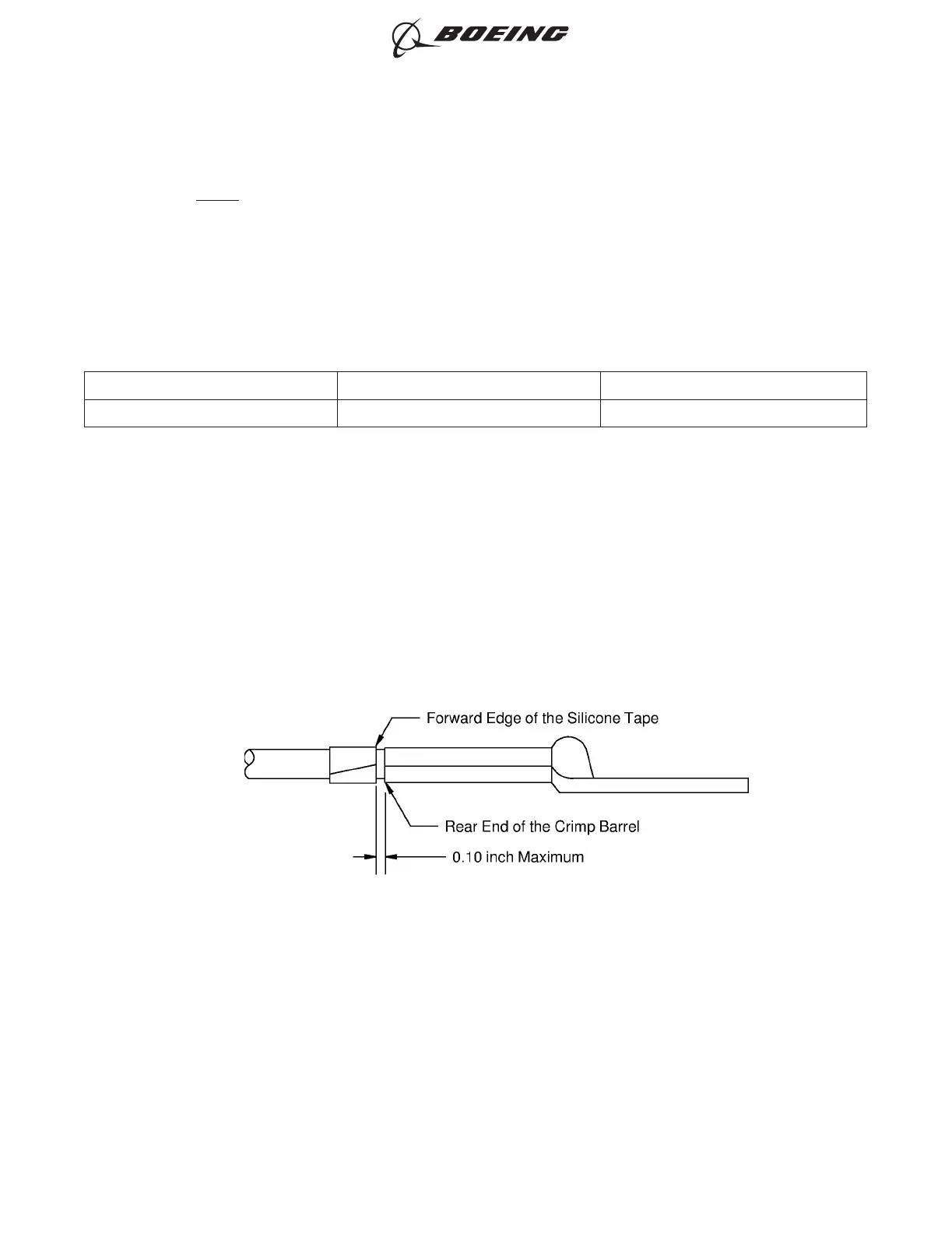
(4) If a tape is specified with the insulation sleeve, wind 3 layers of the tape on the wire at the rear
end of the crimp barrel. Refer to Figure 11.
Make sure that:
• The layers of tape make a 100 percent overlap
• The tape does not make an overlap with the terminal lug
• The forward end of the tape does not extend farther than 0.1 inch from the rear end of the
crimp barrel.
(5) If a cold shrinkable sleeve is specified for the insulation of the terminal lug assembly, install the
sleeve. Refer to Figure 12.
POSITION OF THE TAPE ON THE WIRE
Figure 11
ASSEMBLY OF BACT12BC, BACT12BD, BACT12BE, BACT12BF AND BACT12BG ALUMINUM
TERMINALS
707, 727-787
STANDARD WIRING PRACTICES MANUAL
20-30-07
Page 10
Oct 15/2015D6-54446
ECCN 9E991 BOEING PROPRIETARY - See title page for details