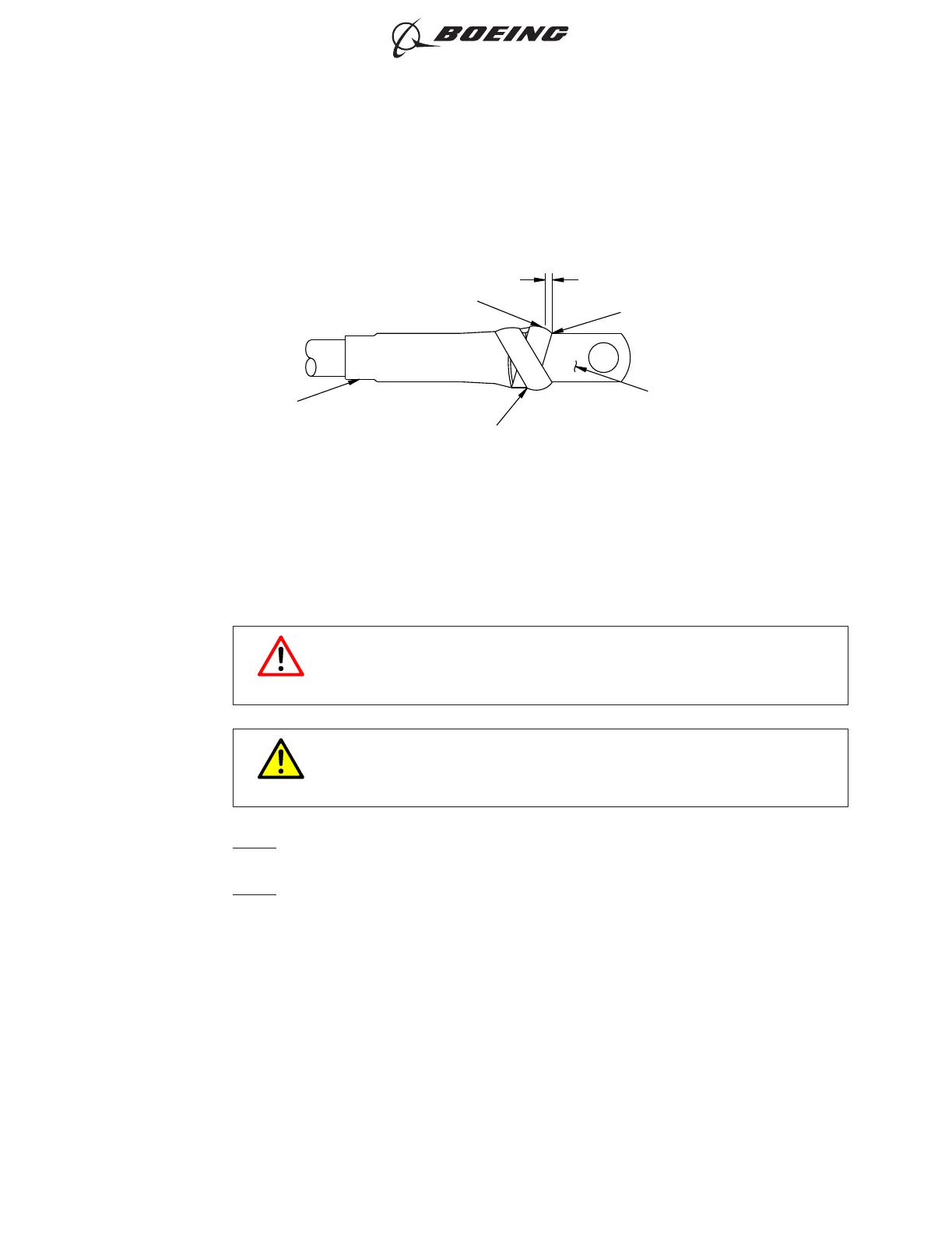
(c) Examine the extension of the terminal lug insulation. Refer to Figure 15.
Make sure that:
1) The tape makes an overlap with the notch of the tongue of the terminal lug.
2) The tape does not extend farther than 0.025 inch forward from the edge of the notch.
(8) Crimp Tool Preparation
This Subject gives the procedures for preparation of the Hydraulic Crimp Tool.
(a) Preparation of the 58422-1 Hydraulic Crimp Tool
Refer to Figure 16, Figure 17 and Figure 18.
WARNING
DO NOT ACCIDENTLY PRESS THE FOOT PEDAL OR THE HANDLE
CONTROL WHILE THE DIES ARE REMOVED OR INSTALLED. INJURY
TO PERSONNEL CAN OCCUR.
CAUTION
DO NOT INSTALL DIFFERENT DIES FROM DIFFERENT DIE SETS IN A
CRIMP TOOL HEAD. DAMAGE TO THE EQUIPMENT CAN OCCUR.
NOTE: The standard configuration of the crimp tool dies is the nest as the stationary die
and the indenter as the moving die.
NOTE: As an alternative to make the crimp operation easier, the indenter can be used as
the stationary die and the nest can be used as the moving die.
0.025 INCH MAXIMUM
BOTTOM SURFACE OF
THE TONGUE
FORWARD EDGE OF THE TAPE
0.5 INCH SILICONE TAPE
INSULATION SLEEVE
EDGE OF NOTCH
2528890 S0000597241_V1
Position of the Tape on the Bottom Surface of the Tongue
Figure 15
ASSEMBLY OF BACT12BC TE ALUMINUM TERMINALS
707, 727-787
STANDARD WIRING PRACTICES MANUAL
20-30-08
Page 13
Oct 15/2017D6-54446
ECCN 9E991 BOEING PROPRIETARY - See title page for details