BPswitch Operators Manual
11 / 413
Input 4 on the BPswitch card corresponds to ‘3’ on Tally Box (LX & LS Only)
Input 5 on the BPswitch card corresponds to ‘4’ on Tally Box (LS Only)
Input 6 on the BPswitch card corresponds to ‘5’ on Tally Box (LS Only)
Network Input 1 corresponds to ‘6’ on Tally Box
Network Input 2 corresponds to ‘7’ on Tally Box
Each relay contact is rated at 6 amps at 120 volts AC or 28 volts DC. The
convenient screw terminals can accept cable from 12 to 22 AWG.
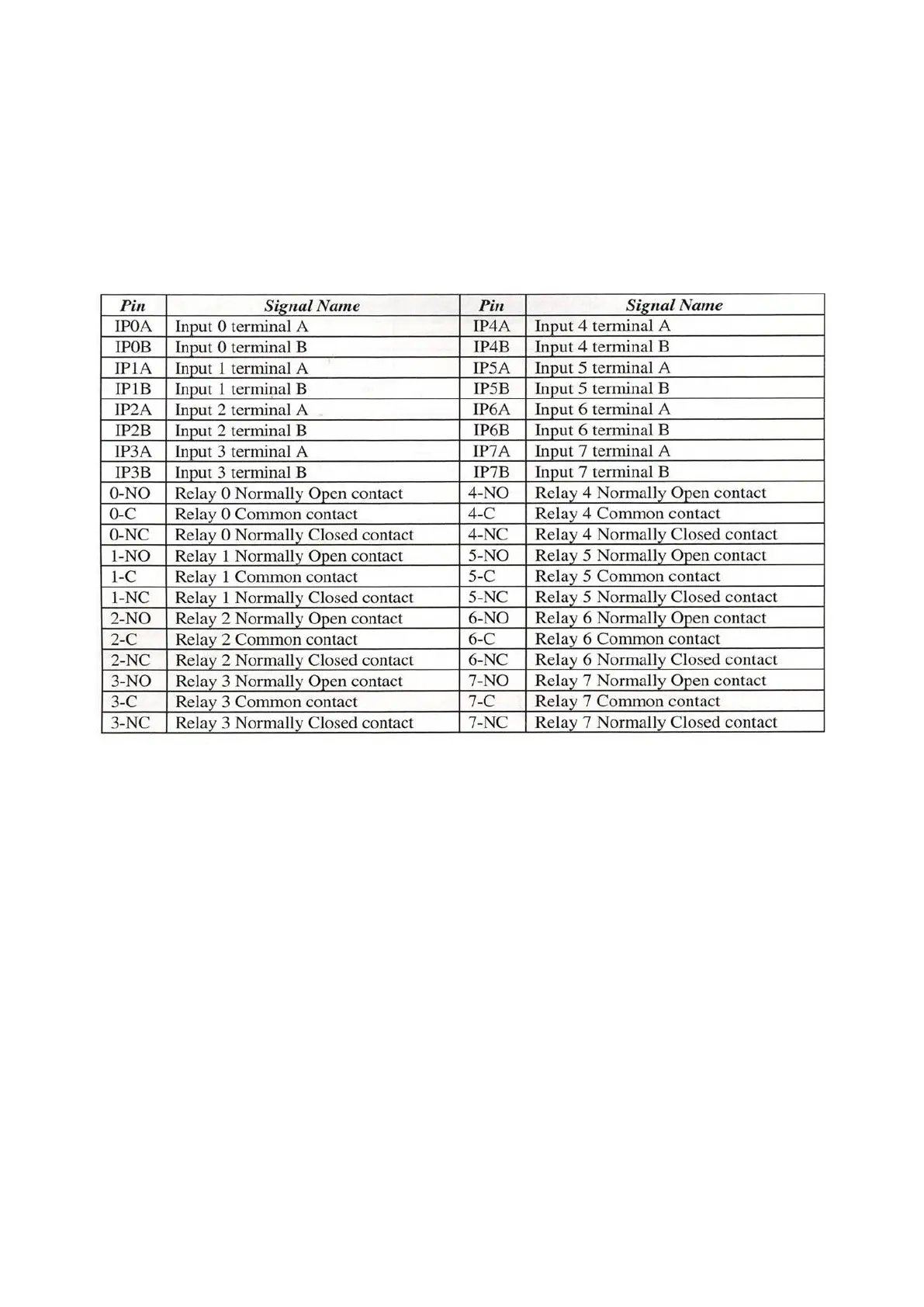
NOTE: The ‘Inputs Contacts’ (IP A/B) are for General Purpose Inputs (GPI). The ‘Relay Contacts’
are for Tally. ‘NO’ for Normally Open, ‘C’ for Common or Ground, ‘NC’ for Normally Closed.
Installing Optional 8 port Tally Box
Run a set of wires from each terminal in the Tally Box to each terminal on your
camera/camera unit, one to Program and the other to the Ground, as shown
below. ‘NO’ (Normally Open) goes to Program and ‘C’ (Common) goes to Ground.
‘NC’ (Normally Closed) is not used. The Tally box uses one of the Servers USB
ports, and needs to be plugged into an electrical socket with the supplied power
supply.