BPswitch Operators Manual
270 / 413
- Direct control from the Broadcast Pix to the Telemetrics camera head. This
configuration allows for up to 10 cameras to be controlled by Broadcast Pix.
No shading/white balance control is offered when controlled directly,
camera/lens manufacturers remote panels may be needed for shading. When
controlling more than 1 camera, the Telemetrics Serial Transfer Switch, STS-
12, is needed to connect multiple serial cables.
- Broadcast Pix control of the camera systems through the Telemetrics Studio
Software, CPS-ST-S. This configuration allows for up to 50 cameras to be
controlled through the Telemetrics CPS-ST-S software application. Full
shading/white balance control is provided by the CPS-ST-S, and not by
Broadcast Pix. A single serial cable from the Broadcast Pix Server to the
CPS-ST-S is needed.
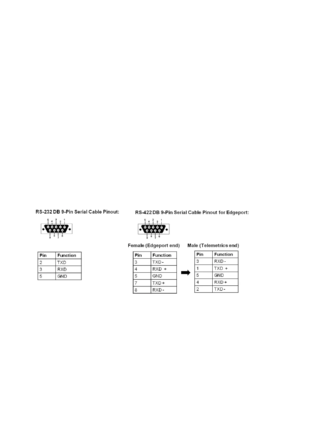
The control for both configurations can can either be connected using a RS-232 or
RS-422 serial connection and are selectable in the Camera Control Settings menu
in BPswitcher. With a RS-232 connection, the maximum cable length can be
extended to 15 meters (50 feet), while the RS-422 connection extends this further
to 1200 meters (4000 feet).
There are no COM ports out of the Broadcast Pix Server, a 4/8 port USB extender
(Edgeport) is required to control cameras serially.
Telemetrics Wiring Configurations
Single Camera Telemetrics Configuration:
To connect Lens and other Camera Control cables, refer to the Telemetrics
owners manual.