BPswitch Operators Manual
13 / 413
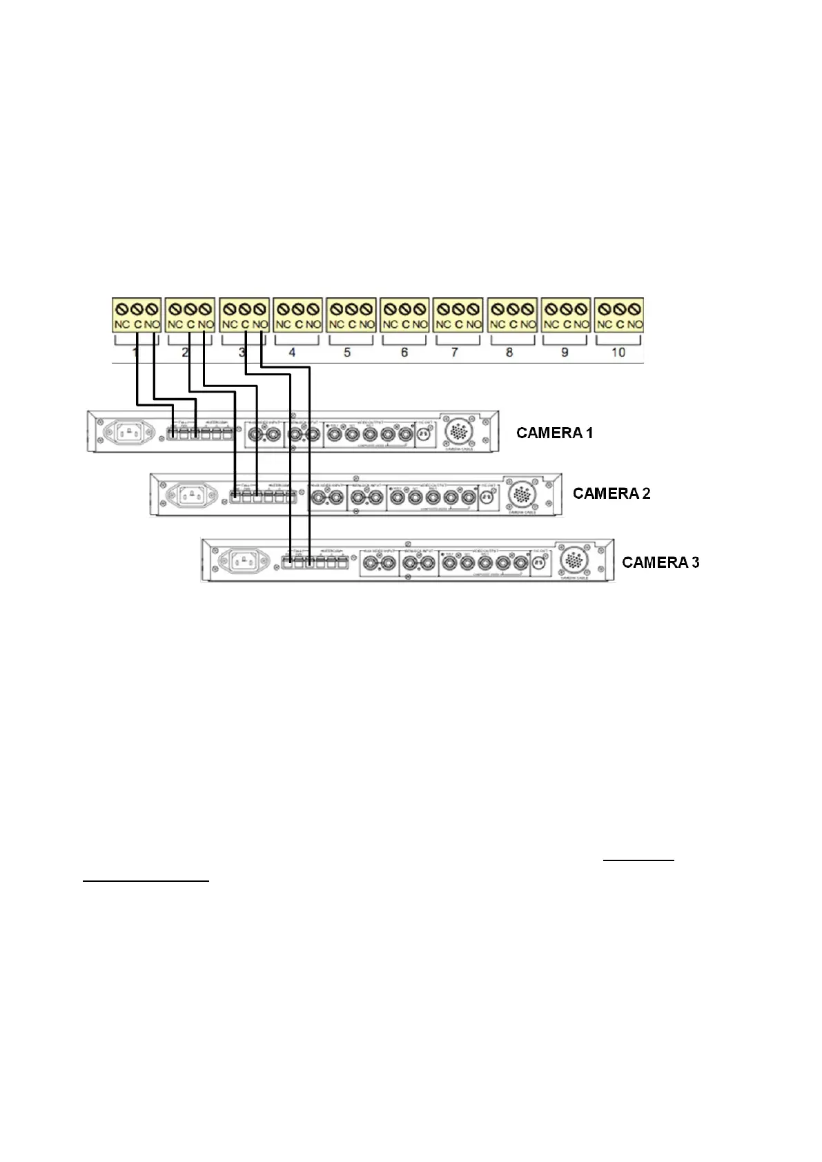
below. ‘NO’ (Normally Open) goes to Program and ‘C” (Common) goes to
Ground. ‘NC’ (Normally Closed) is not used.
2.
Plug in the supplied USB B to USB A cable. One end in any port of the Server,
the other in the USB IN port of the tally box.
3.
Plug in the supplied power supply into Power In 9VDC port of the tally box. 2
LEDs should illuminate: PWR should be solid green when the power is plugged
in, USB solid green when connected to the Server and flashing green when the
Server is communicating to the tally box.
* Camera Control Unit will vary depending on manufacturer.
NOTE: The Tally Box does not supply any voltage for tally. Voltage must be provided by your
Camera Control Units or other source. The Tally Box only opens and closes the tally circuit.
Check your Camera Control Unit’s user manual for more information.
Activating the Optional Tally Box Drivers
When the tally box option is purchased it may be plugged in and connected, as the
drivers are already pre-loaded on all BPswitch systems from the factory. However,
it is recommended that you start the InstaCal Program and test the tally box prior
to using it with your system,
In addition you will need to install an option code, as described in Installing
System Options, which can be obtained from Technical Support, if not already
provided on the Option Code Card.
To activate the drivers:
1.
Connect the tally box to the workstation with the supplied USB cable and plug-
in the power with the supplied power supply to an electrical socket.
2.
To confirm the installation, navigate to the Start Menu, All Programs,
Measurement Computing, InstaCal. This will launch the InstaCal software
program, as shown below left.