BPswitch Operators Manual
12 / 413
* Camera Control Unit will vary depending on manufacturer.
2 LEDs should illuminate when power is connected: External Power should be
solid green, Status solid green when connected to the Server and flashing green
when the Server is communicating to the tally box.
NOTE: The Tally Box does not supply any voltage for tally. Voltage must be provided by your
Camera Control Units or other source. The Tally Box only opens and closes the tally circuit.
Check your Camera Control Unit’s user manual for more information.
Installing Optional 24 port Tally Box
The Measurement Computing USB-ERB24 tally box provides 24 relay contacts for
up to 8 camera/sources and 16 GPOs . It fits into a standard 19” wide rack and
comes standard with racking ears and uses convenient screw terminals that
accepts cable from 12 to 22 AWG. Each contact is rated a 6 amps at 240 volts
AC. The box uses one of the Servers USB ports, and needs to be plugged into an
electrical socket with the supplied power supply. This tally box does not have
GPIs, the 8 port tally/GPI box may be used in conjunction with this tally box.
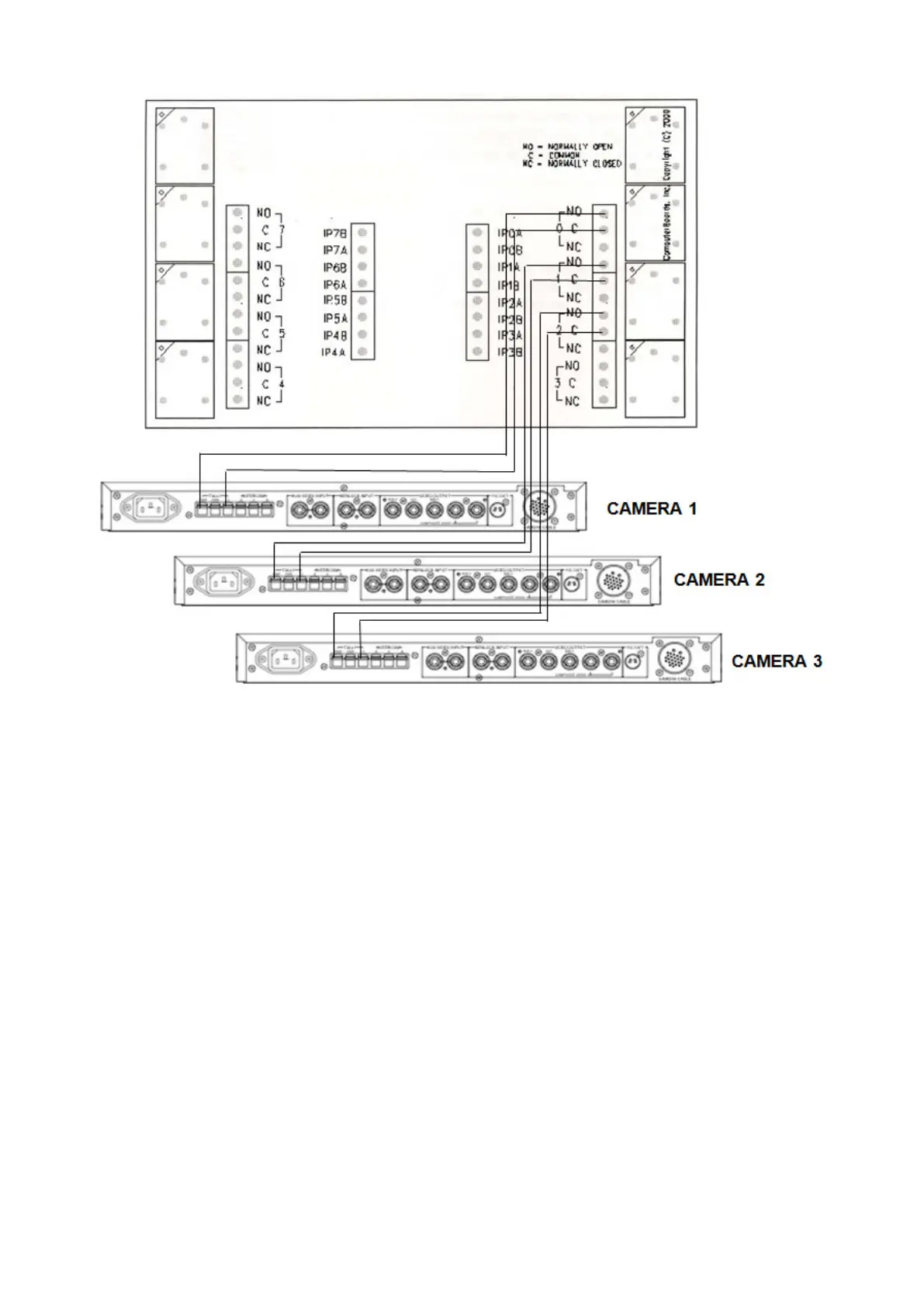
Installing the Optional Tally Box:
1.
Run a set of wires from each terminal in the Tally Box to each terminal on your
camera/camera unit, one to Program and the other to the Ground, as shown