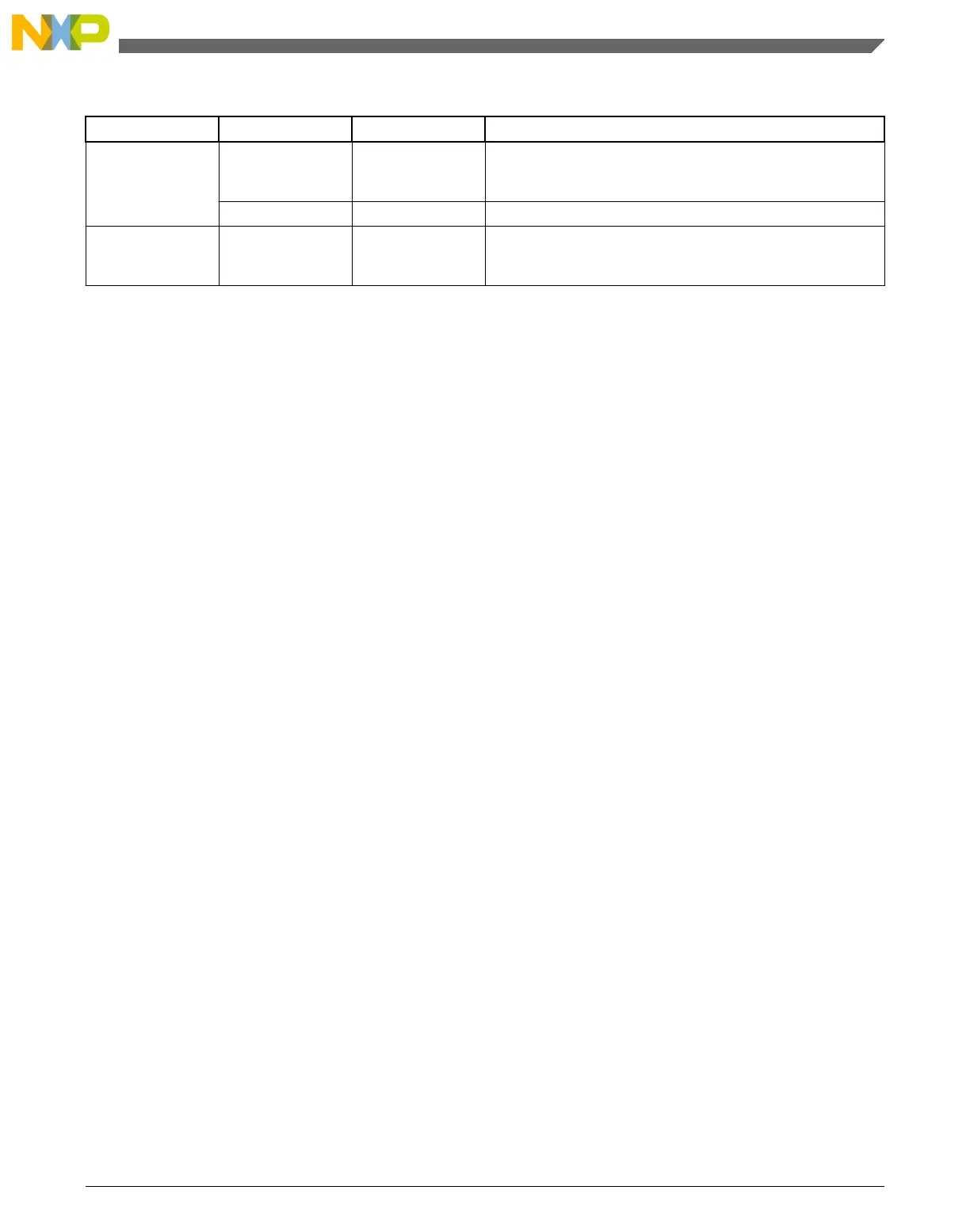
Table 13-7. Power mode transition triggers (continued)
Transition # From To Trigger conditions
10 RUN LLS PMPROT[ALLS]=1, PMCTRL[STOPM]=011, Sleep-now or
sleep-on-exit modes entered with SLEEPDEEP set, which is
controlled in System Control Register in ARM core.
LLS RUN Wakeup from enabled LLWU input source or RESET pin.
11 VLPR LLS PMPROT[ALLS]=1, PMCTRL[STOPM]=011, Sleep-now or
sleep-on-exit modes entered with SLEEPDEEP set, which is
controlled in System Control Register in ARM core.
1. If debug is enabled, the core clock remains to support debug.
2. If PMCTRL[STOPM]=000 and STOPCTRL[PSTOPO]=01 or 10, then only a Partial Stop mode is entered instead of STOP
3. If PMCTRL[STOPM]=000 and STOPCTRL[PSTOPO]=00, then VLPS mode is entered instead of STOP. If
PMCTRL[STOPM]=000 and STOPCTRL[PSTOPO]=01 or 10, then only a Partial Stop mode is entered instead of VLPS
13.4.2 Power mode entry/exit sequencing
When entering or exiting low-power modes, the system must conform to an orderly
sequence to manage transitions safely. The SMC manages the system's entry into and exit
from all power modes. The following diagram illustrates the connections of the SMC
with other system components in the chip that are necessary to sequence the system
through all power modes.
Chapter 13 System Mode Controller (SMC)
KL25 Sub-Family Reference Manual, Rev. 3, September 2012
Freescale Semiconductor, Inc. 227

 Loading...


