Bit 7 COCO 0 Read-only flag which is set when a conversion completes.
Bit 6 AIEN 1 Conversion complete interrupt enabled.
Bit 5 DIFF 0 Single-ended conversion selected.
Bit 4:0 ADCH 00001 Input channel 1 selected as ADC input channel.
RA = 0xxx
Holds results of conversion.
CV = 0xxx
Holds compare value when compare function enabled.
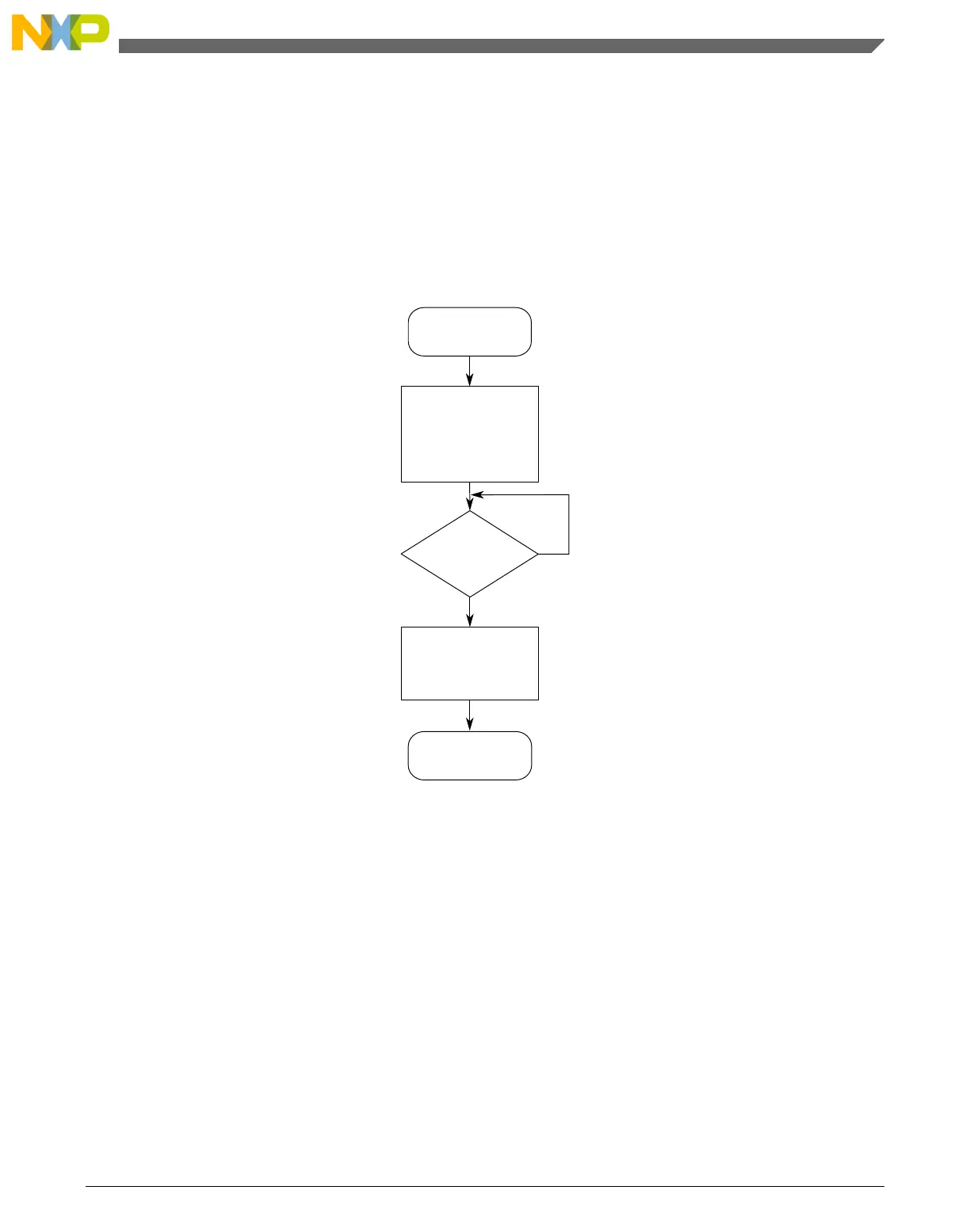
Reset
No
Yes
Check
SC1n[COCO]=1?
Initialize ADC
CFG1 = 0x98
SC2 = 0x00
SC1n = 0x41
Continue
Read Rn
to clear
SC1n[COCO]
Figure 28-64. Initialization flowchart example
28.6 Application information
The ADC has been designed to be integrated into a microcontroller for use in embedded
control applications requiring an ADC.
28.6.1 External pins and routing
Chapter 28 Analog-to-Digital Converter (ADC)
KL25 Sub-Family Reference Manual, Rev. 3, September 2012
Freescale Semiconductor, Inc. 501

 Loading...


