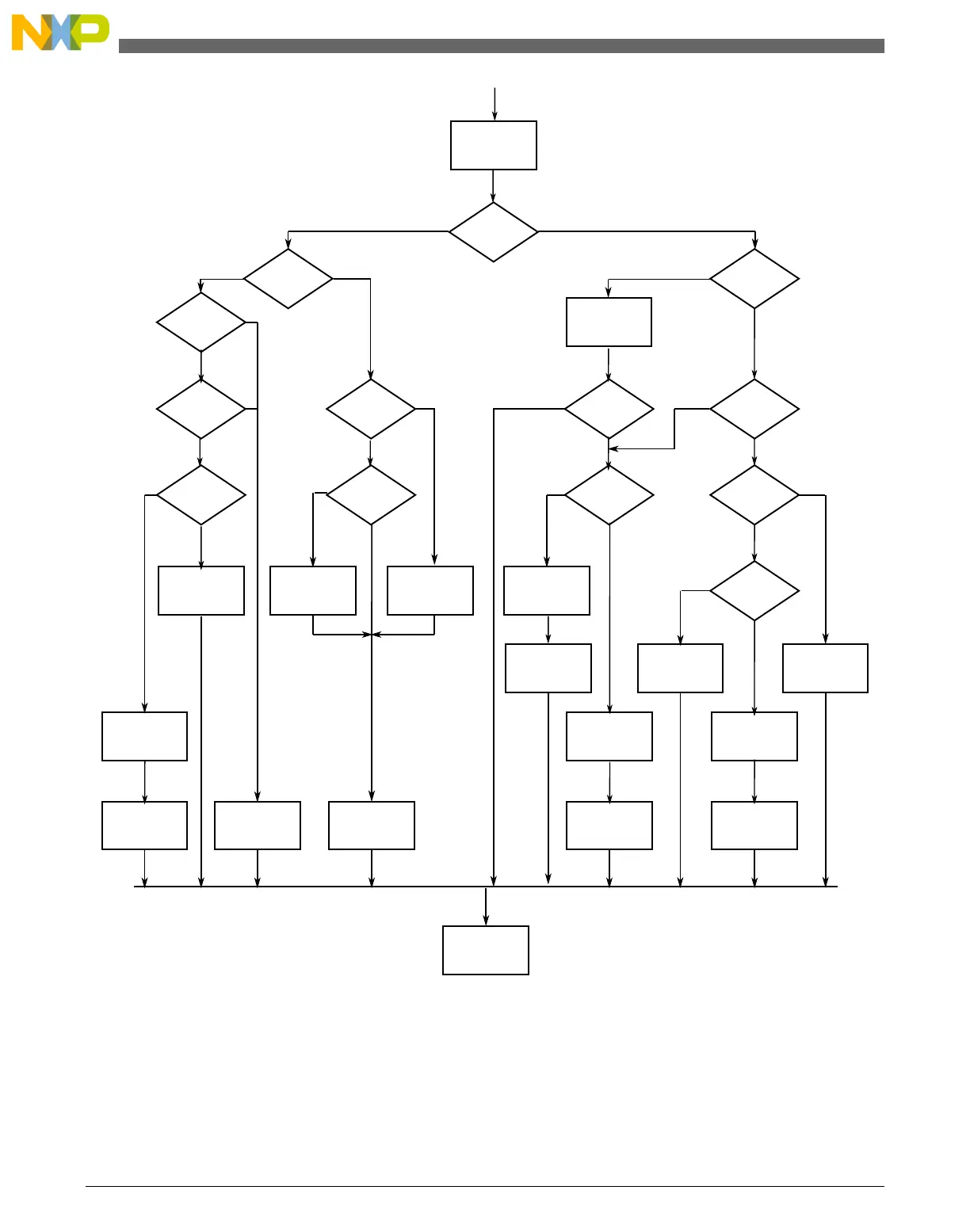
Clear IICIF
Master
mode?
Tx/Rx?
Arbitration
lost?
IIAAS=1?
Tx/Rx?
ACK from
receiver?
SRW=1?
IIAAS=1?
Clear ARBL
2nd to
last byte to be
read?
Last byte
to be read?
RXAK=0?
Last byte
transmitted?
End of
address cycle
(master Rx)?
Write next
byte to Data reg
Set TXACK
Generate stop
signal (MST=0)
Write data
to Data reg
Set TX mode
Transmit
next byte
Read data from
Data reg
and store
RTI
Switch to
Rx mode
Set Rx mode
Switch to
Rx mode
Dummy read
from Data reg
Generate stop
signal (MST=0)
Read data from
Data reg
and store
Dummy read
from Data reg
Dummy read
from Data reg
N
Y
N
N
N
N
N
N
Y
Y
Y
Y
Y
(read)
N (write)
N
Y
RxTx
Rx
Tx
Y
N
Address transfer
see note 1
Data transfer
see note 2
N
Y
Y
Y
Notes:
1. If general call is enabled, check to determine if the received address is a general call address (0x00).
If the received address is a general call address, the general call must be handled by user software.
2. When 10-bit addressing addresses a slave, the slave sees an interrupt following the first byte of the extended address.
Ensure that for this interrupt, the contents of the Data register are ignored and not treated as a valid data transfer.
Figure 38-42. Typical I2C interrupt routine
Initialization/application information
KL25 Sub-Family Reference Manual, Rev. 3, September 2012
718 Freescale Semiconductor, Inc.

 Loading...


