UARTx_S1 field descriptions (continued)
Field Description
0 No parity error.
1 Parity error.
39.2.6 UART Status Register 2 (UARTx_S2)
This register contains one read-only status flag.
When using an internal oscillator in a LIN system, it is necessary to raise the break
detection threshold one bit time. Under the worst case timing conditions allowed in LIN,
it is possible that a 0x00 data character can appear to be 10.26 bit times long at a slave
running 14% faster than the master. This would trigger normal break detection circuitry
designed to detect a 10-bit break symbol. When the LBKDE bit is set, framing errors are
inhibited and the break detection threshold increases, preventing false detection of a 0x00
data character as a LIN break symbol.
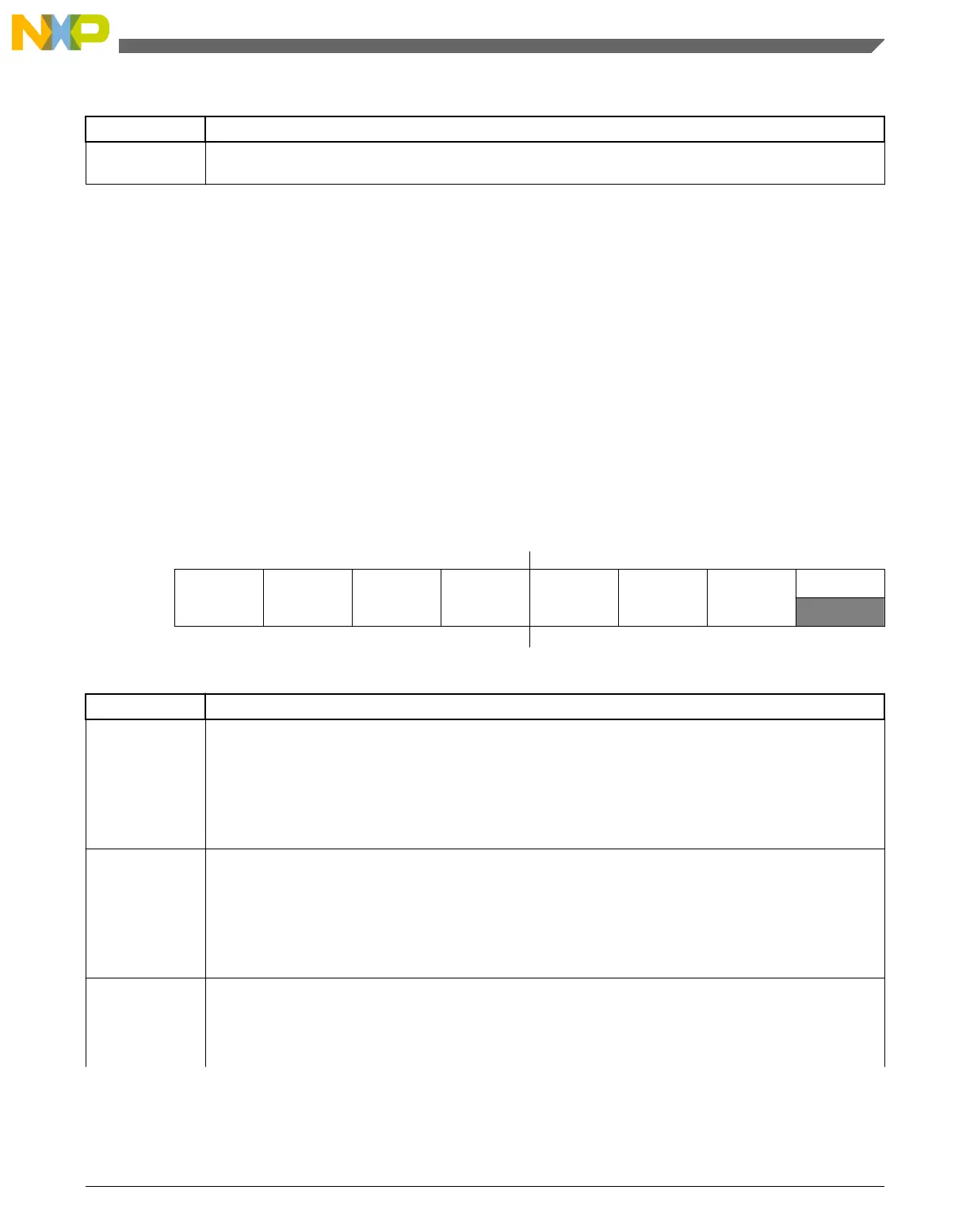
Address: Base address + 5h offset
Bit 7 6 5 4 3 2 1 0
Read
LBKDIF RXEDGIF MSBF RXINV RWUID BRK13 LBKDE
RAF
Write
Reset
0 0 0 0 0 0 0 0
UARTx_S2 field descriptions
Field Description
7
LBKDIF
LIN Break Detect Interrupt Flag
LBKDIF is set when the LIN break detect circuitry is enabled and a LIN break character is detected.
LBKDIF is cleared by writing a 1 to it.
0 No LIN break character has been detected.
1 LIN break character has been detected.
6
RXEDGIF
UART _RX Pin Active Edge Interrupt Flag
RXEDGIF is set when an active edge, falling if RXINV = 0, rising if RXINV=1, on the UART _RX pin
occurs. RXEDGIF is cleared by writing a 1 to it.
0 No active edge on the receive pin has occurred.
1 An active edge on the receive pin has occurred.
5
MSBF
MSB First
Setting this bit reverses the order of the bits that are transmitted and received on the wire. This bit does
not affect the polarity of the bits, the location of the parity bit or the location of the start or stop bits. This bit
should only be changed when the transmitter and receiver are both disabled.
Table continues on the next page...
Chapter 39 Universal Asynchronous Receiver/Transmitter (UART0)
KL25 Sub-Family Reference Manual, Rev. 3, September 2012
Freescale Semiconductor, Inc. 731

 Loading...


