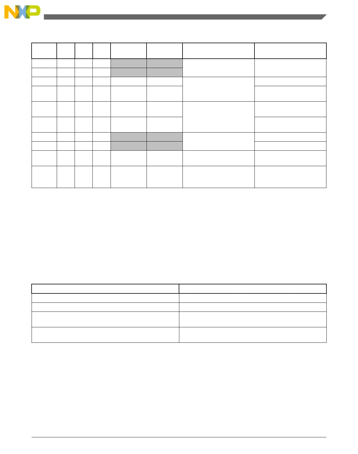
Table 29-16. Comparator sample/filter maximum latencies (continued)
Mode #
CR1[
EN]
CR1[
WE]
CR1[
SE]
CR0[FILTER
_CNT]
FPR[FILT_P
ER]
Operation Maximum latency
1
2A 1 0 0 0x00 X Continuous Mode T
PD
2B 1 0 0 X 0x00
3A 1 0 1 0x01 X Sampled, Non-Filtered mode T
PD
+ T
SAMPLE
+ T
per
3B 1 0 0 0x01 > 0x00 T
PD
+ (FPR[FILT_PER] *
T
per
) + T
per
4A 1 0 1 > 0x01 X Sampled, Filtered mode T
PD
+ (CR0[FILTER_CNT] *
T
SAMPLE
) + T
per
4B 1 0 0 > 0x01 > 0x00 T
PD
+ (CR0[FILTER_CNT] *
FPR[FILT_PER] x T
per
) + T
per
5A 1 1 0 0x00 X Windowed mode T
PD
+ T
per
5B 1 1 0 X 0x00 T
PD
+ T
per
6 1 1 0 0x01 0x01 - 0xFF Windowed / Resampled
mode
T
PD
+ (FPR[FILT_PER] *
T
per
) + 2T
per
7 1 1 0 > 0x01 0x01 - 0xFF Windowed / Filtered mode T
PD
+ (CR0[FILTER_CNT] *
FPR[FILT_PER] x T
per
) +
2T
per
1. T
PD
represents the intrinsic delay of the analog component plus the polarity select logic. T
SAMPLE
is the clock period of the
external sample clock. T
per
is the period of the bus clock.
29.9 CMP interrupts
The CMP module is capable of generating an interrupt on either the rising- or falling-
edge of the comparator output, or both. The following table gives the conditions in which
the interrupt request is asserted and deasserted.
When Then
SCR[IER] and SCR[CFR] are set The interrupt request is asserted
SCR[IEF] and SCR[CFF] are set The interrupt request is asserted
SCR[IER] and SCR[CFR] are cleared for a rising-edge
interrupt
The interrupt request is deasserted
SCR[IEF] and SCR[CFF] are cleared for a falling-edge
interrupt
The interrupt request is deasserted
29.10 DMA support
Normally, the CMP generates a CPU interrupt if there is a change on the COUT. When
DMA support is enabled by setting SCR[DMAEN] and the interrupt is enabled by setting
SCR[IER], SCR[IEF], or both, the corresponding change on COUT forces a DMA
Chapter 29 Comparator (CMP)
KL25 Sub-Family Reference Manual, Rev. 3, September 2012
Freescale Semiconductor, Inc. 533

 Loading...


