30.4.4 DAC Control Register (DACx_C0)
Address: 4003_F000h base + 21h offset = 4003_F021h
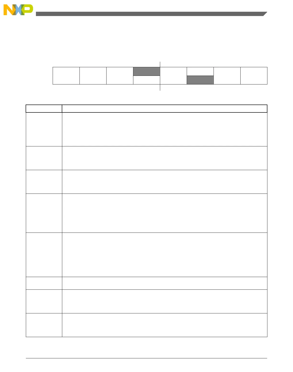
Bit 7 6 5 4 3 2 1 0
Read
DACEN DACRFS
DACTRGSE
L
0
LPEN
0
DACBTIEN DACBBIEN
Write
DACSWTRG
Reset
0 0 0 0 0 0 0 0
DACx_C0 field descriptions
Field Description
7
DACEN
DAC Enable
Starts the Programmable Reference Generator operation.
0 The DAC system is disabled.
1 The DAC system is enabled.
6
DACRFS
DAC Reference Select
0 The DAC selects DACREF_1 as the reference voltage.
1 The DAC selects DACREF_2 as the reference voltage.
5
DACTRGSEL
DAC Trigger Select
0 The DAC hardware trigger is selected.
1 The DAC software trigger is selected.
4
DACSWTRG
DAC Software Trigger
Active high. This is a write-only field, which always reads 0. If DAC software trigger is selected and buffer
is enabled, writing 1 to this field will advance the buffer read pointer once.
0 The DAC soft trigger is not valid.
1 The DAC soft trigger is valid.
3
LPEN
DAC Low Power Control
NOTE: See the 12-bit DAC electrical characteristics of the device data sheet for details on the impact of
the modes below.
0 High-Power mode
1 Low-Power mode
2
Reserved
This field is reserved.
This read-only field is reserved and always has the value 0.
1
DACBTIEN
DAC Buffer Read Pointer Top Flag Interrupt Enable
0 The DAC buffer read pointer top flag interrupt is disabled.
1 The DAC buffer read pointer top flag interrupt is enabled.
0
DACBBIEN
DAC Buffer Read Pointer Bottom Flag Interrupt Enable
0 The DAC buffer read pointer bottom flag interrupt is disabled.
1 The DAC buffer read pointer bottom flag interrupt is enabled.
Chapter 30 12-bit Digital-to-Analog Converter (DAC)
KL25 Sub-Family Reference Manual, Rev. 3, September 2012
Freescale Semiconductor, Inc. 541

 Loading...


