42.1.2 Modes of operation
This module supports the following operation modes.
Table 42-1. Operating modes
Mode Description
Stop and low power stop TSI module is fully functional in all of the stop modes as long
as TSI_GENCS[STPE] is set. The channel specified by
TSI_DATA[TSICH] will be scanned upon the trigger. After
scan finishes, either end-of-scan or out-of-range interrupt can
be selected to bring MCU out of low power modes.
Wait TSI module is fully functional in this mode. When a scan
completes, TSI submits an interrupt request to CPU if the
interrupt is enabled.
Run TSI module is fully functional in this mode. When a scan
completes, TSI submits an interrupt request to CPU if the
interrupt is enabled.
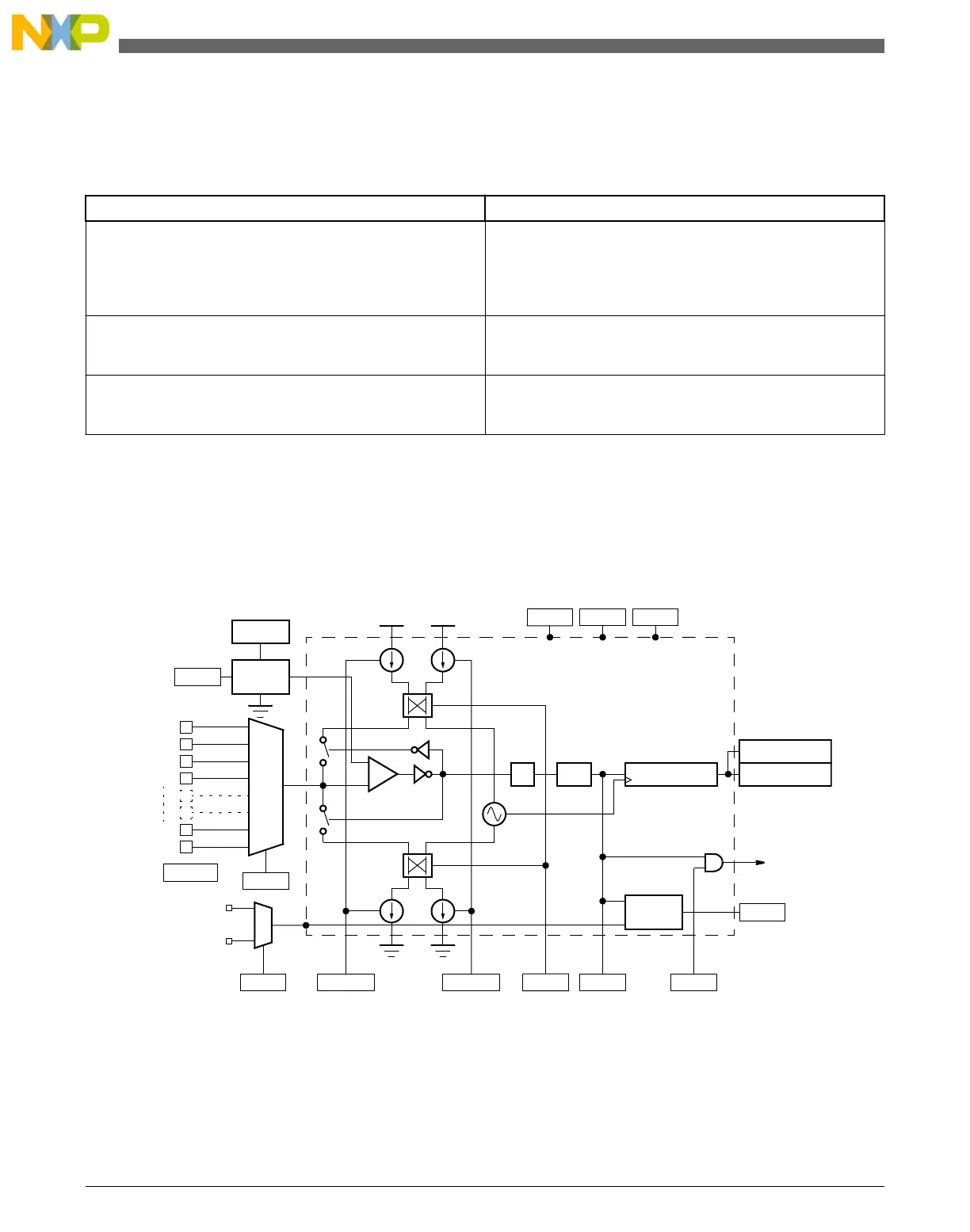
42.1.3 Block diagram
The following figure is a block diagram of the TSI module.
ANALOG MUX
TSI0
TSI1
TSI2
TSI3
TSI14
TSI15
+
–
2
PS
Reference Clock
Interrupt
TSIIEN
Int. 1.8V
DVOLT
TSICH
EOSF
Write SWTS “1”
TSI_PENx
MUX
STM EXTCHRG
NSCN 16-bit Counter
REFCHRG
TSI_CNTH
TSI_CNTL
Voltage
SCNIP
Control
Logic
Divider
CURSW
Electrode
Reference
Oscillator
Oscillator
TSIEN TSIIEN STPE
Hardware Trigger
Figure 42-1. TSI module block diagram
Introduction
KL25 Sub-Family Reference Manual, Rev. 3, September 2012
786 Freescale Semiconductor, Inc.

 Loading...


