CMPx_DACCR field descriptions (continued)
Field Description
0 V is selected as resistor ladder network supply reference V.
in1in
1 V is selected as resistor ladder network supply reference V.
in2in
5–0
VOSEL
DAC Output Voltage Select
Selects an output voltage from one of 64 distinct levels.
DACO = (V
in
/64) * (VOSEL[5:0] + 1) , so the DACO range is from V
in
/64 to V
in
.
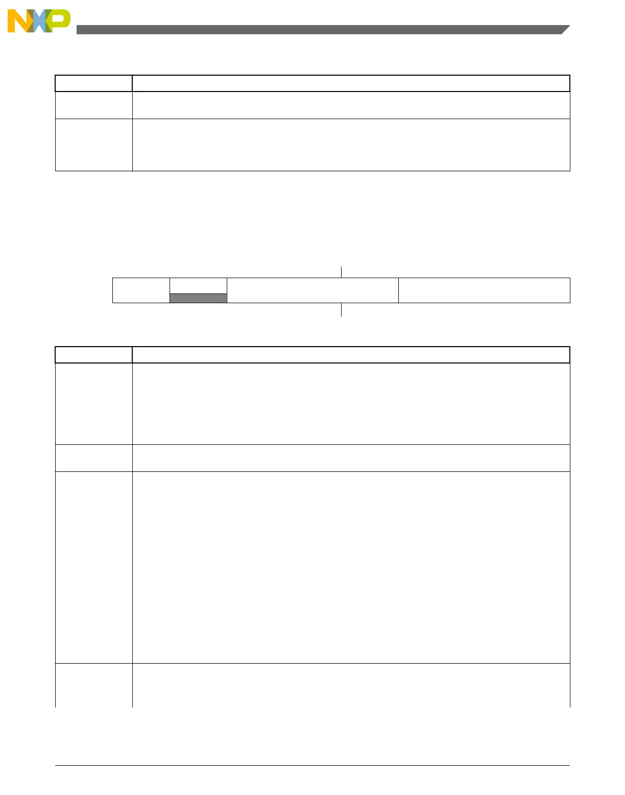
29.7.6 MUX Control Register (CMPx_MUXCR)
Address: 4007_3000h base + 5h offset = 4007_3005h
Bit 7 6 5 4 3 2 1 0
Read
PSTM
0
PSEL MSEL
Write
Reset
0 0 0 0 0 0 0 0
CMPx_MUXCR field descriptions
Field Description
7
PSTM
Pass Through Mode Enable
This bit is used to enable to MUX pass through mode. Pass through mode is always available but for
some devices this feature must be always disabled due to the lack of package pins.
0 Pass Through Mode is disabled.
1 Pass Through Mode is enabled.
6
Reserved
This field is reserved.
This read-only field is reserved and always has the value 0.
5–3
PSEL
Plus Input Mux Control
Determines which input is selected for the plus input of the comparator. For INx inputs, see CMP, DAC,
and ANMUX block diagrams.
NOTE: When an inappropriate operation selects the same input for both muxes, the comparator
automatically shuts down to prevent itself from becoming a noise generator.
000 IN0
001 IN1
010 IN2
011 IN3
100 IN4
101 IN5
110 IN6
111 IN7
2–0
MSEL
Minus Input Mux Control
Determines which input is selected for the minus input of the comparator. For INx inputs, see CMP, DAC,
and ANMUX block diagrams.
Table continues on the next page...
Chapter 29 Comparator (CMP)
KL25 Sub-Family Reference Manual, Rev. 3, September 2012
Freescale Semiconductor, Inc. 519

 Loading...


